Moldex3D Boundary Layer Mesh (BLM) is one of the most suitable mesh technologies for CAE application in plastic injection molding. The supporting mesh types include tetra and multiple-layer BLM to approach flow and heat behaviors near the mold cavity surface. Moldex3D can ensure the solid mesh layer amount across the thickness direction and allows to further increase the layers for higher accuracy requirement. The powerful meshing kernel allows users to apply different mesh types for different attributes such as part, runner, insert and cooling channel.
BLM parameters such as mesh size, boundary layer count and offset ratio, are individually adjustable as needed. Moldex3D provides default values to all mesh parameters that are applicable for plenty of general cases. However, to approach advanced phenomena with more decent molding simulation, it is suggested to modify parameters based on different model characters. The following will guide to set mesh parameters for different modeling essentials.
Step-by-step BLM parameters Setup before mesh generation
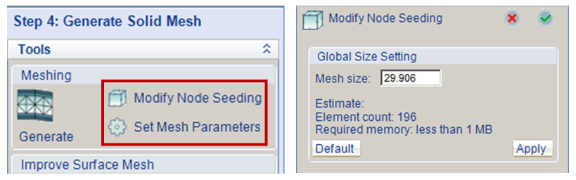
Step1: After all model components are prepared in Moldex3D Designer, directly click Generate to start mesh generation, or click Modify Node Seeding and Set Mesh Parameter in Step 4 (in the software) to modify the seeding and mesh parameters for default setting.
Note: If using Moldex3D Studio, the corresponding functions are Seeding and Parameter in the Mesh Tab.
Launch the node seeding and BLM mesh parameter setting panel
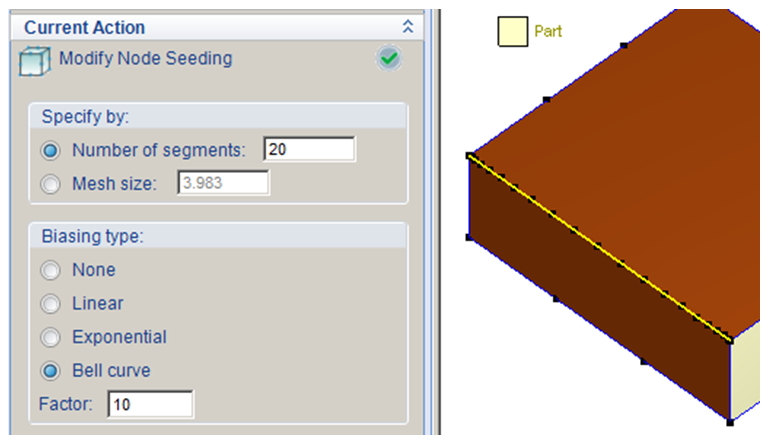
Step2.1 In the beginning of node seeding, set the global mesh size or leave it as Moldex3D’s default setting based on the model size. Click Apply to preview the seeding result and then click OK to continue with local refine of node seeding. Select the edges and specify the seeding density by Number of segments or Mesh size (average length per segment) and press Enter to show the result.
Note: In Biasing type, it allows non-uniform node distribution with customized factors to further refine seeding locally on the edge.
Refine node seeding locally and set non-uniform distribution
Step2.2: It is suggested to refine the node seeding especially around the location with more complex melt flow behaviors, as well as for some component attributions. The recommended attributions and locations of node refine are listed as below.
| Attribute/Location | Minimum Segment Number |
| Melt Entrance (Circumference) | 24 |
| Pin Gate (Circumference) | 40 |
| Edge Gate (Short Edge) | 7 |
| Pin Gate (Circumference) | 5 |
| Part Insert (Short Edge) | 8 |
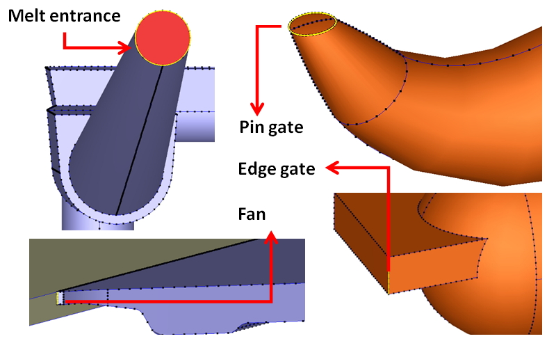
Refine the seeding around important features
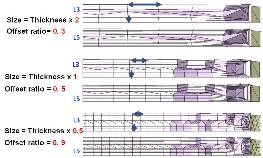
Step3 In Set BLM Parameters, choose BLM count (Mesh type) and specify the value of Boundary layer offset ratio according to different object attributes. Since more BLM count will lead to thinner BLM elements and worse aspect ratio, it is suggested to increase the offset ratio at the same time. Also, the offset ratio should be increased when the surface mesh is smaller so that effective boundary layer thickness can be attained. Please refer to the second figure below.
Note: The maximum count of BLM can be increased up to 11 in Options. However it could lead to bad final mesh quality (too small aspect ratio) even with enlarged offset ratio in some cases.
Note: The mesh structure of line components (Runner or Cooling Channel) can be set in Curve Meshing.
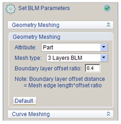
Set BLM count and offset ratio according to different object attributes