
Gate design is a key part in plastic injection molding process since it will have a direct impact on the occurrence of the undesirable product surface defects such as weld lines and air traps. In order to get the best results, the gate design is changed quite frequently during the simulation process; therefore, enhancing the efficiency of gate position changes can save a great deal of effort and time spent in the simulation analysis.
To help users speed up this product and mold design process, Moldex3D provides a useful gate optimization tool, Gate Wizard, which allows users to automatically create 9 types of gates, including an edge gate, a fan gate, a tunnel gate and a cashew gate. Furthermore, the newly-enhanced Moldex3D Gate Wizard provides an intelligent and intuitive interface, Gate Attributes, that increases the efficiency of gate optimization. Moldex3D users can now utilize Gate Attributes to adjust gate locations with more freedom The new enhanced features will be introduced below.
Add gates at the end of the runner
If the runner system is already well designed, users can click the point at the end of the runner, and set it as the starting point of the gate. Then Moldex3D will automatically find the projected point on the product surface extending in the same direction as the runner from the end of the runner point, and set it as the end of the gate. The complete gate will be created accordingly.
Take a cashew gate as an example, when a runner system has already been created (Fig. 1), and users can utilize Gate Wizard to click the point at the end of the runner to add a gate. If the “Locate at side of part” item is checked, Moldex3D will create a gate on the projected point on the product surface extending in the same direction as the runner from the end of the runner point (Fig. 2). If “Locate at side of part” is not checked, the cashew gate will be located on the point on the product surface along the melt direction parallel to the parting surface (Fig. 3).
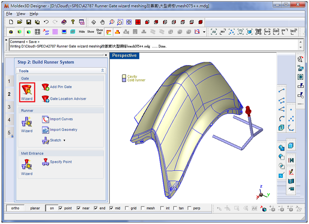 Fig. 1 A runner system has been created
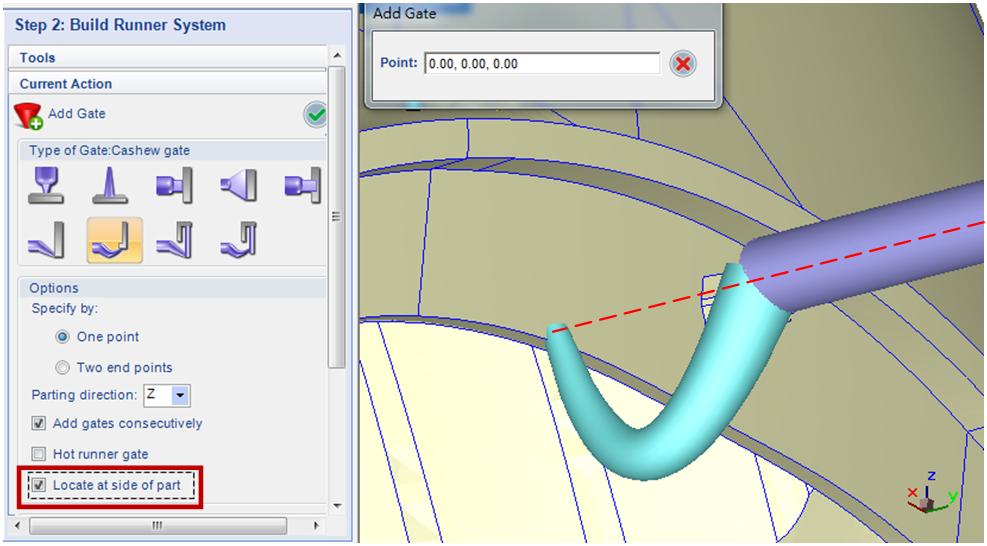 Fig. 2 Check “Locate at side of part”, and the gate will be created on the projected point on the product surface extending in the same direction as the runner from the end of the runner point
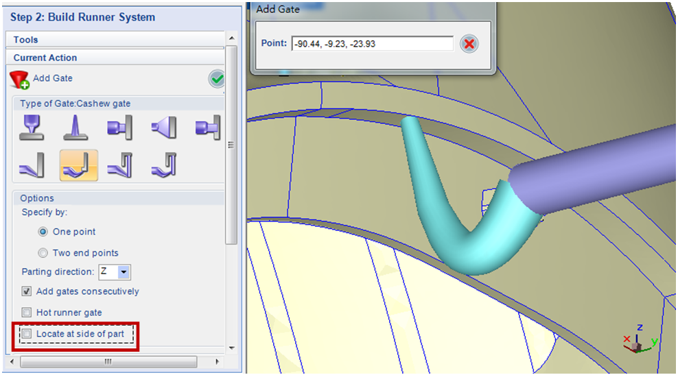 Fig. 3 If “Locate at side of part” is not checked, the gate will be located on the point on the product surface along the melt direction parallel to the parting surface
Interactive interface enabling gate location modifications
After setting the gates, users can further fine-tune the gate locations in the Gate Attributes interface.
- Moldex3D is able to create cross-section lines along the melt direction and parting direction. By observing the cross-section lines which different gate locations correspond to, users can adjust the gates to the best locations (Fig. 4).
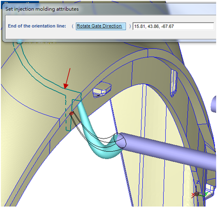 Fig. 4 Moldex3D is able to display cross-section lines (as the arrow shows) for users to adjust gate locations
- Apart from the gate locations, the melt directions can also be modified. After the previous step, the gate locations can still be adjusted a few more times (Fig. 5). Moreover, users can adjust the melt directions while the gate locations are fixed (Fig. 6).
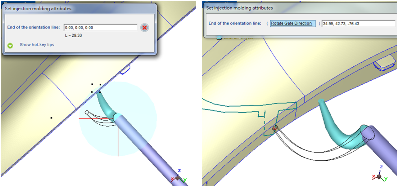 Fig. 5 After modifying the melt direction (left), users can adjust the gate location by observing the cross-section lines (right)
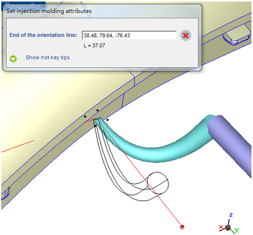 Fig. 6 Adjust the melt direction while the gate location is fixed
In short, as Moldex3D’s pre-processing interface makes the gate design changes more efficient and accurate, users can attain accurate simulation results with ease and effectively apply them in the actual injection molding product development.