
Moldex3D Designer BLM (Boundary Layer Mesh) is a powerful pre-processing tool designed for complex geometries. Over a course of a year, extensive research efforts were devoted in furthering the technology for mesh generation, a significant breakthrough in Designer BLM has been made available in the latest Moldex3D’s 2016 version, Moldex3D R14. Now Designer BLM supports “Non-matching Mesh” technology, which can greatly benefit the simulations of multi-component molding (MCM) process. With the help of this meshing technology, users no longer have to manually adjust the mesh nodes when meshing the part inserts which enables a more efficient workflow for mesh generation.
Why do we need “Non-matching Mesh Technology”?
Multi-component molding (MCM) is a common manufacturing process used across various industry sectors. Traditionally speaking, when preparing a mesh for MCM simulation, the mesh nodes on the contact face between the part and the part insert should be interconnected to ensure the continuity in simulation results. Therefore, users have to manually adjust the mesh at the contact face between the part and the part insert to make sure the mesh nodes for these two areas are aligned; yet, are of different components. It is not only a time-consuming task but also a proper mesh, interconnecting these two components are hard to attain.
Now, with the introduction of “Non-matching Mesh” technology, users can skip the manual efforts on mesh matching completely and go straight to the simulation. Using non-matching mesh technology can still provide continuous simulation results and capture the intricate, interconnected mechanism between the part and the part inserts. As the model shown in Fig.1, the contact surface mesh between the part and the part insert is not continuous, but the cooling and warpage analysis results could still display the continuity in temperature distribution and deformation through Non-Matching mesh technology.
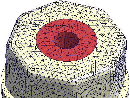 Fig. 1 Non-matching mesh of the part and the part insert
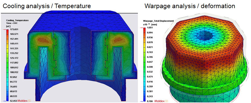 Fig. 2 The result continuity in temperature distribution and and deformation in cooling and warpage analysis
Non-matching Mesh Reliability Verification
Take a car mount made from multi-component injection process as an example (Fig. 3). This case was validated through the cooperation of Moldex3D and TomTom Technology. As shown in Fig.4 (left), Moldex3D R13 uses a matching mesh; a continuous solid mesh between the second-shot and the part insert has to be generated. In addition, a higher resolution mesh is needed in R13. Therefore, it will have more mesh elements and the analysis time will be longer. In the contrary, Moldex3D R14 can tolerate a lower-resolution mesh and support both non-matching and matching meshes, as shown in Fig.4 (middle and right).
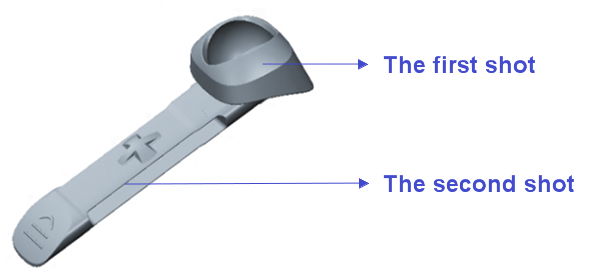 Fig. 3 A car mount in the car navigation system
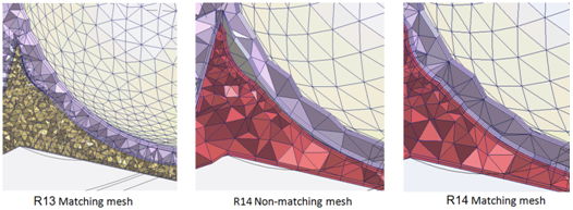 Fig. 4 Solid mesh generated by Moldex3D R13 (left) and R14 (middle and right)
Based on the three different meshing set-ups mentioned above, we then compare the deformation values at seven different nodes (Fig. 5). As shown in Fig, 6, the analysis result of non-matching mesh in R14 exhibits a high level of accuracy and indicates a similar deformation result in trend with the result of R13.
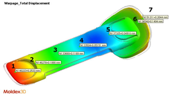 Fig. 5 The deformation values at seven different nodes
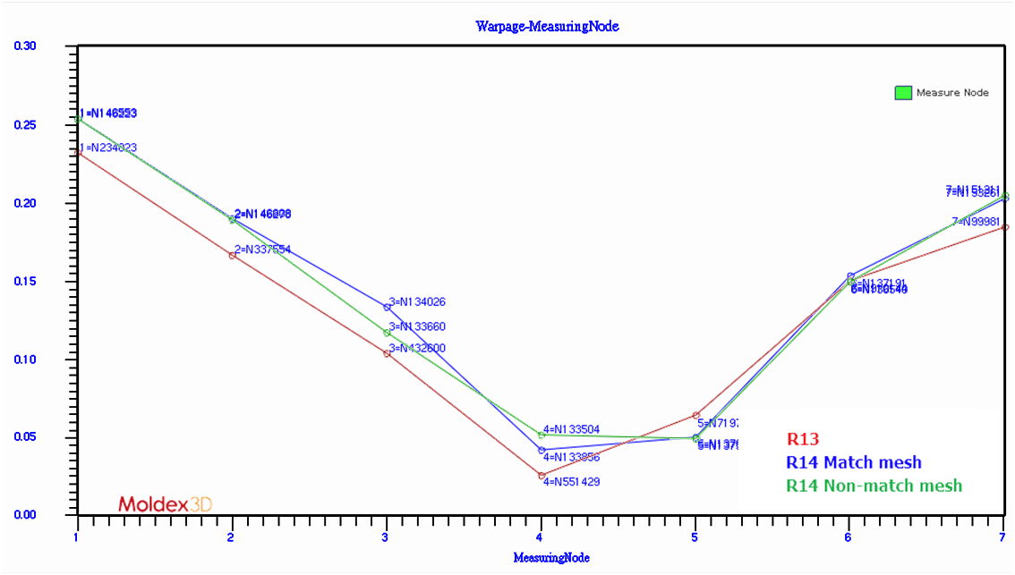 Fig. 6 The warpage analysis results of three different mesh types have similar trends.
In conclusion, “Non-matching Mesh” technology in Moldex3D Designer BLM can be widely applied in MCM process simulations. It not only supports the general simulation analysis (Flow, Pack, Cool, Warp) but also supports the core-shift analysis. Non-matching Mesh technology is applicable for all the modules Designer BLM supports and provides accurate analysis results with a more efficient workflow, which is particularly useful when simulating a model with numerous part inserts. In addition, Non-matching Mesh technology is an easy-to-use tool which allows a quicker learning curve of mastering the arts of mesh preparation in Designer BLM, even for a new Moldex3D user!