
Victor Sun, Senior Engineer at the R&D Division, CoreTech System (Moldex3D)
During the flip-chip encapsulation process, the capillary underfill (CUF) with dispensing process is used for protection. The process is shown in Fig. 1. A dispenser is used to inject the encapsulation materials at the edge of the chip. Through capillarity, the liquid encapsulation material will continuously flow to cover the whole gap between the chip and substrate. During the dispensing process, apart from the melt amount control, it is a usual way to heat the chassis carrying the substrate so that the viscosity of encapsulation will be decreased rapidly while it drops between the chip and substrate. Then, the melt will rapidly flow and fill the gaps.
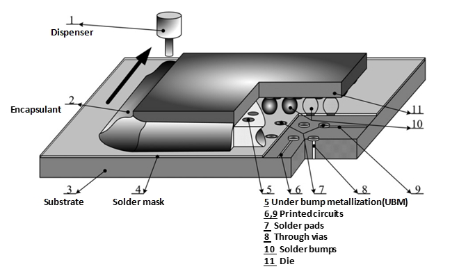
Fig. 1 The capillary underfill with the dispensing process [1]
The driving force of the underfill process is capillary, so the description of surface tension and wall adhesion condition input are the main essential factors in simulation. The capillary is composed of the surface tension and melt front distribution based on the gas-liquid interaction. The wall adhesion between the filler material and interface (the substrate) is described by the contact angle under steady condition. As Young’s equation shows in Fig. 2, the contact angle represents the balance condition of the interface between the gas, liquid, and solid phase. Thus, the contact angle is an important property that controls the steady-state of the balance of multi phases.
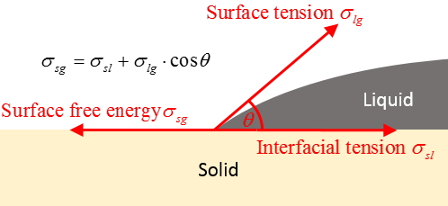
Fig. 2 Young’s equation
Due to the nature of thermoset plastics, the underfill material cannot be reprocessed after encapsulation. Moreover, the trial and error cost at the development stage is high because both the capillary-driven flow and the curing process are time-consuming works. To reduce the development cost, adopting CAE simulation is an efficient choice to find out the best solution of design control with good agreement with requests.
The underfill materials are costly, hence the mass control is also an important issue. Apart from the dispensing area, the underfill can also flow into the bump zone from the edge of the chip due to the overflow caused by creeping. Therefore, simulation of overflow not only help understanding mass control of underfill, but also the analysis of void locations caused by melt front. As shown in Fig. 3, after the dispensing, the melt flow is majorly driven by the capillary, gravity and the fluid viscosity. Thus, the material amount should contain the filling through the capillary force, the edge flow through creeping and the extension flow by spreading force when the melt sink on the substrate. Therefore, to study the use of material comprehensively through CAE simulation, all three kinds of flow should be considered in the analysis.
The simulation and experiment results in Fig. 4 show the consideration of the dispensing and creeping flow area in the simulation shall be unneglectable. Because of the neglection of the effects of the dispensing and creeping flow area in the traditional simulation, the simulation result shows the lack of the underfill from edge flow. To attain more qualified simulation results, Moldex3D 2020 Capillary Underfill Module provides a comprehensive analysis. In this module, the 3D model with flip-chip product details (including the bump distribution and dies as shown in Fig. 5) is used. The dispensing settings support multiple paths, the dispensing amount of every path as well as the start time and speed of the dispenser movement (Fig. 6). The material parameter setting supports the contact angle between the filling material and other materials (Fig. 7) to simulate the polymer behaviors affected by environmental factors.
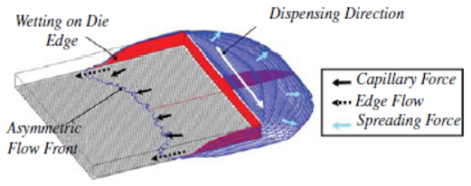
Fig. 3 The relation chart of the melt flow [2]
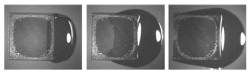
The experiment [3]
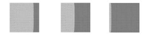
The traditional simulation results [3]
The Moldex3D 2020 simulation results
Fig. 4 The creep-up behaviors in the experiment and simulation
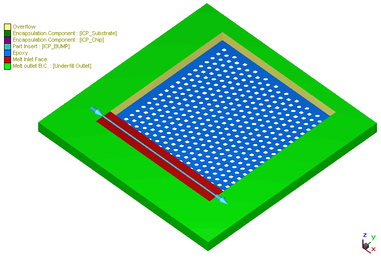
Fig. 5 The 3D Model
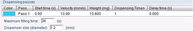
Fig. 6 The dispensing settings
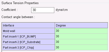
Fig. 7 The capillarity settings
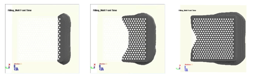
Moldex3D simulation includes the dispensing process during the flow, the underfill of the bump area and the flow outside of the dies (creep-up and extension flow) as shown in Fig. 8. Fig. 9 shows the melt sink behavior changes along with the underfill process in the dispensing area. From the simulation results, we can tell the necessity of considering the comprehensive physical behaviors in the scientific simulation.
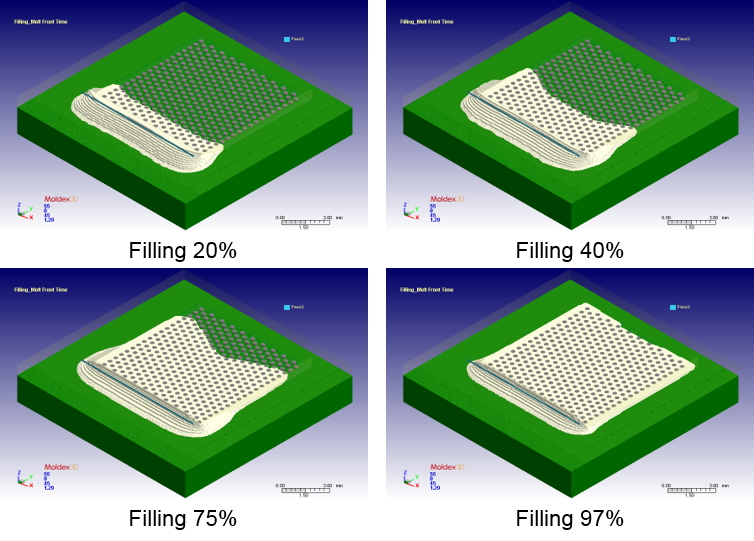
Fig. 8 The filling analysis
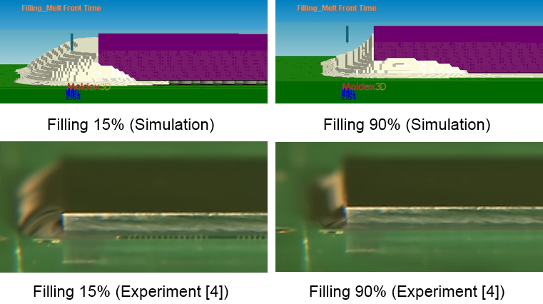
Fig. 9 The schematic diagram of the changes in the dispensing area.
As shown, Moldex3D 2020 can help users to understand the effect of dispensing control and creeping behaviors on the underfill process at the design stage. As a result, the purpose to make the required design through the mass control of underfill and avoiding the costly trial-and-error process can be accomplished.
Reference
- Hui Wang, Huamin Zhou, Yun Zhang, Dequn Li and Kai Xu Three-dimensional simulation of underfill process in flip-chip encapsulation, Computers & Fluids 44 (2011) 187–201
- S.W.M. etc., 3-D Numerical Simulation and Validation of Underfill Flow of Flip-Chips. IEEE Transactions On Components, Packaging and Manufacturing Technology, Vol. 1, No. 10, October, (2011), pp. 1517-1522
- Sung-Won Moon, Zhihua Li, Shripad Gokhale, and Jinlin Wang, IEEE TRANSACTIONS ON COMPONENTS, 3-D Numerical Simulation and Validation of Underfill Flow of Flip-Chips (2011)
- Nordson ASYMTEK: The NexJet System – Flip Chip Underfill: https://www.youtube.com/watch?v=hdxjWJ2c0ao