Philip Chang, Chef Engineer at Technical Support Team, Moldex3D
Sometimes we assume perfect contact with no thermal resistance between adjacent objects to simplify cooling simulations. However, microscopic gaps always exist that will cause resistance in real cases. Moreover, the condition of polymer contacting mold units can vary and is complex through the molding process.
In light of this, Moldex3D Studio provides setting tools for heat transfer coefficient (HTC) boundary condition (BC) for users to easily consider the thermal resistance of the interfaces.
Moldex3D HTC Wizard provides a friendly and convenient workflow, so users can easily assign the HTC values for the interfaces with various materials, contact pressure, roughness, or gaps. Also, users can set the HTC values for different molding stages independently according to the required applications.
Step 1 Get started
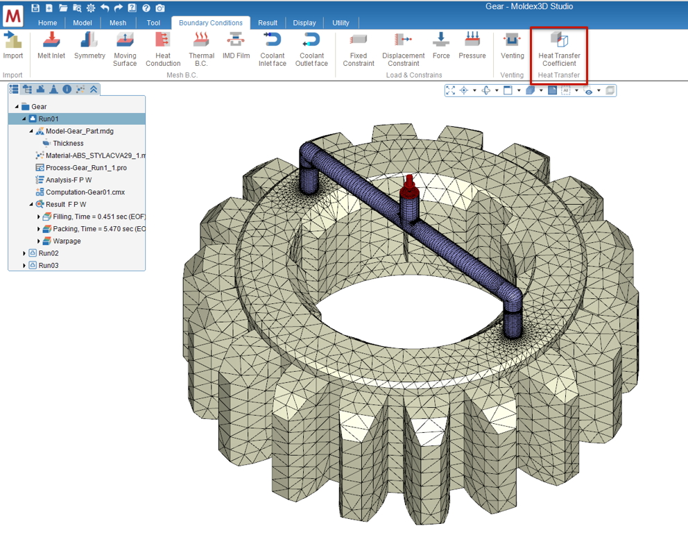
Prepare a model. Till Final Check launched after the mesh generation or importing a mesh file (MFE), click the Heat Transfer Coefficient in the Boundary Condition tab to launch the wizard tool and specify the BC Name.
Note: HTC BC is not supported in eDesign models.
Step 2 Assign HTC BC
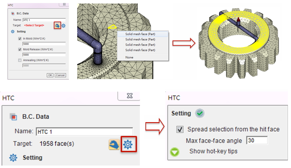
Select the surface elements on the mesh model to assign HTC BC. Use the multiple selections (Shift key) and selection spread features to more efficiently assign the BC of the surface elements. The selection mode is initially ON when creating BC and one can click Select (the hand icon) to disable or enable it again.
Note: Click Setting (the gear icon) near Select to control the selection spread.
Note: For the Fast Cool mesh, HTC BC will be effective ONLY on the surfaces between the part and part insert.
Step 3 Set HTC value
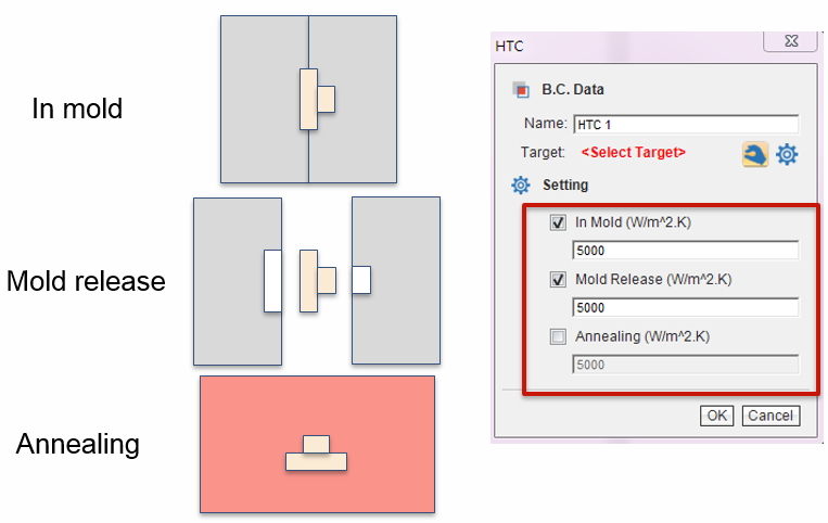
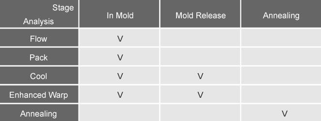
In the HTC Setting, three molding stages, In Mold, Mold Release, and Annealing, are supported by different analysis types. Check a stage to enable it and specify a proper HTC value to modify the thermal resistance on the selected surface mesh. Uncheck a stage to apply thermal resistance as the global default depending on the interface type and corresponding molding stage.
Note: HTC BC is not supported (not effective) in the Standard Warp analysis.
Step 4 Modify HTC BC data
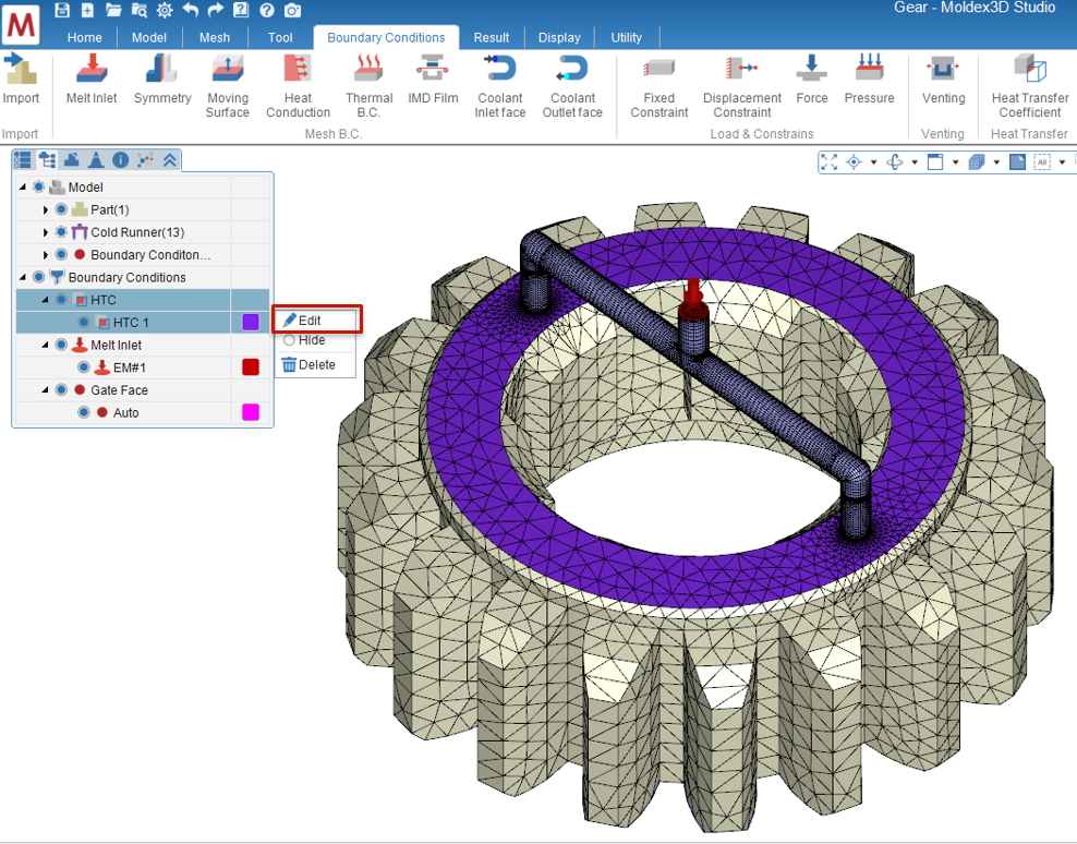
Users can click the HTC Name from the Boundary Conditions on the Model Tree to highlight the assigned HTC BC in the Display Window. Also, users can right-click on the HTC name and click Edit to recall the HTC Wizard for BC modification or click Delete to remove the existing HTC BC if needed.
Step 5 Submit Analysis Job
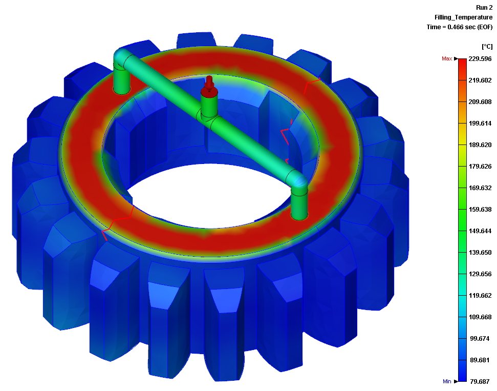
Finish all other analysis settings and submit the analysis job to the solver. After the calculation is done, users can check the temperature distribution in the analysis results that HTC applied. For example, a high-temperature surface exists when the small HTC value is applied.