The performance of injection molded parts can be predicted using FEA software that considers the anisotropy of the materials during processing. We introduced Moldex3D Digimat FEA Interface in the 2013 October newsletter.
In this article we will demonstrate the procedures used to export fiber orientation or foam cell density / size information into Digimat and FEA software.
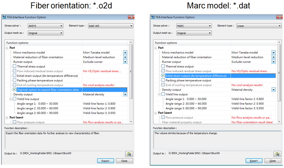
There are two files needed to export fiber orientation data and mesh information to both Digimat and FEA (i.e. Marc) in this demonstration. The *.o2d file is exported from the Moldex3D FEA interface by selecting Digimat export option. The *.dat file for Marc is exported by selecting Marc as the stress solver.
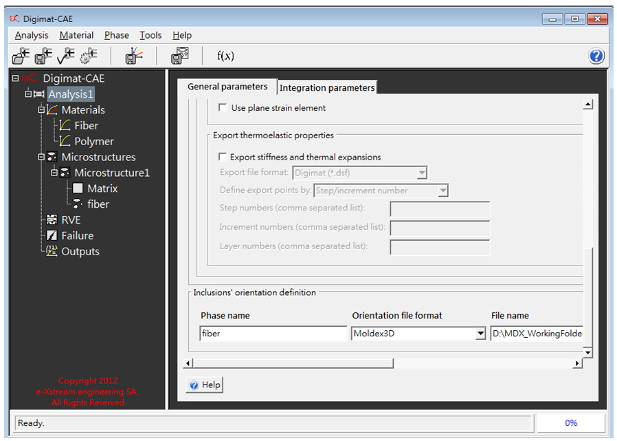
The *.o2d file is then imported by Digimat to define the orientation of the inclusion. The fiber/matrix microstructure needs to be assigned and analyzed prior to importing. The resulting *.marc and *.mat files are needed for Marc analysis.
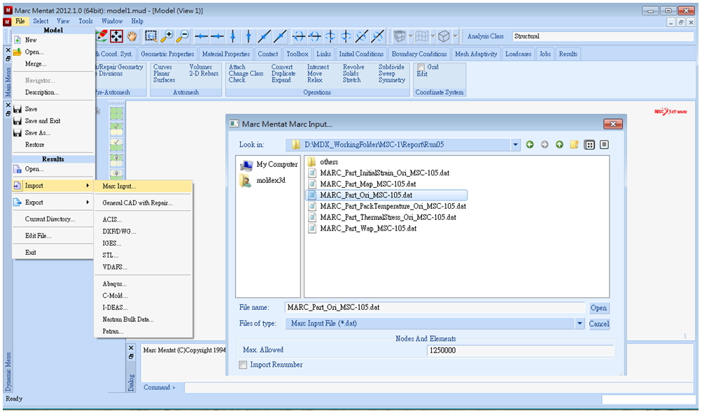
After replacing the *.dat file material card information using the*.mat file, it is then imported into Marc for structural analysis.
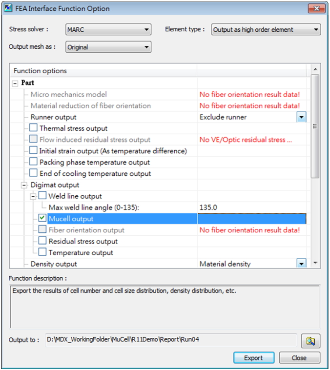
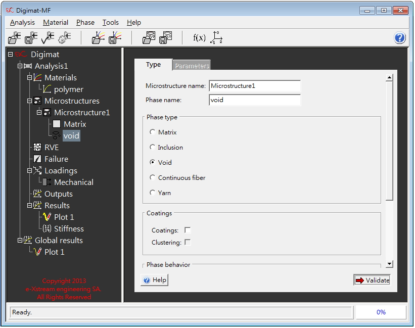
The same procedures are conducted when exporting MuCell® gas bubble microstructure. The exported *.m2d contains the cell density and average size in each element. Void needs to be selected as the second phase inside the polymer matrix when assigning Digimat microstructure composition.