
The easy-to-use interface of Moldex3D Multi-component Molding (MCM) module enables users to quickly and accurately analyze the interaction behavior of different components and further optimize product designs. In the latest release, the Core Shift Analysis adds new “two-way” FSI (Fluid-structure interaction) calculation ability that can simulate real core deformation. In addition, the contact area between the insert and the melt, the layout of the insert and the flow path can also be taken into evaluation to measure the deformation. (Note: two-way FSI needs additional Stress license)
Follow the easy steps below to run Moldex3D Core Shift Analysis with Two-way (FSI) :
Step 1: First, import the whole model, including the part and the insert.
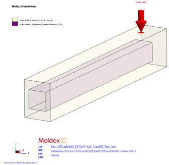 Fig. 1 Import the complete model
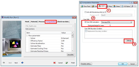
Step 2: Select MCM, and then check the “Core Shift / Two-way (FSI) Computing Mode.” Users can decide how much volume of the melt needed to fill to recalculate the deformation of part inserts.(the default setting is 5%). Then click “Settings” to proceed the constraint boundary condition setting.
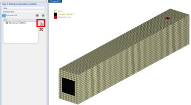
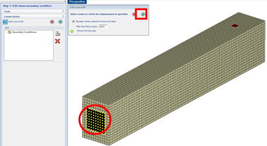
Step 3-1: Click the settings icon “![]() ”under the boundary condition to create a new constraint boundary condition.
”under the boundary condition to create a new constraint boundary condition.
Step 3-2: Click the insert of the outer surface (shown circled in red).
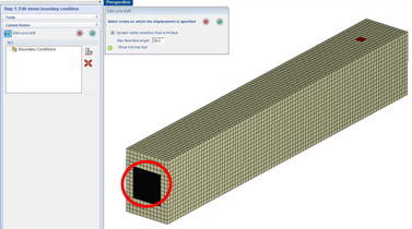
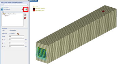
Step 3-3: The surface will then generate yellow nodes. Then click on the check mark to confirm.
Step 3-4: After completing the constraint conditions setting, click the check mark to proceed.
※ Note:
The default setting of the part boundary, the contact area between the wall and the part, is set to fixed boundary conditions. Users do not need any additional settings as the insert will not exceed the boundary during the simulation.
Step 4: The setting is now completed. Below you can see the melt front animation.
 Fig. 2 The Animation of Melt-Front