

- Customer: Lite-On Technology
- Industry: Electronics
- Solution: Moldex3D Advanced Solution Package / FEA Interface
- Region: Taiwan
Executive Summary
Contact Image Sensor (CIS) is a key component of scanners. In this case, the holder of the CIS deformed during the shipment due to the relaxation of residual stress. The distortion of the product led to the separation of the assembled parts, and further degraded the image quality. To address this issue, Lite-On Technology used Moldex3D Advanced Solution Package and Moldex3D FEA Interface incorporating LS-DYNA to explore how the process-induced residual stress affects the product deformation. As a result, Lite-On Technology was able to deliver defect free products on time by utilizing Moldex3D to improve the injection molding process.
Challenges
- Strip products tend to cause flow imbalance
- The deformation range should be under 0.4mm in the horizontal and 0.8mm in the vertical
- The deformation would lead to the separation of the assembled parts
Solutions
With the assistance of Moldex3D and LS-DYNA, the warpage of the product can be reduced by changing different gate locations and process conditions without increasing any cost.
Benefits
- Resolved mold flow-imbalance issues
- Reduced X-axis deformation by 50% (from 0.34 mm to 0.17 mm)
- Solved the separation problem of the assembled parts
- Ensure a high level of product precision
Case Study
The Contact Image Sensor (CIS) holder usually requires high precision. Lite-On Technology combined Moldex3D simulation capabilities and LS-DYNA structural analysis to improve the dimensional stability of the CIS holder of a scanner and ensure it to be within tolerance after molding.
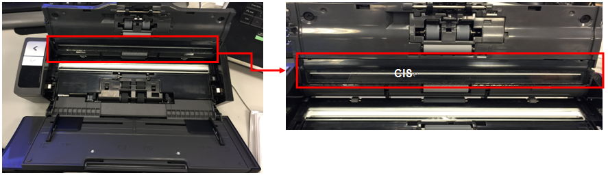 Fig. 1 A CIS holder part (in red circled)
With Moldex3D Advanced Solution Package, Lite-On Technology simulated the molding conditions of the original design based on the traditional injection molding method. The results showed that unbalanced flow and high volumetric shrinkage occurred in the main region of the part and might cause potential deformation risks. At 99.9% of the filling stage, the filling time of the unfilled areas is 0.7 sec slower than the filled area (Fig. 2). The inadequate gate number resulted in concentrated pressure near the melt inlet. It is observed from Fig. 3 that high volumetric shrinkage occurred in the red area near the gates. The local high shrinkage areas can cause internal voids or sink marks when the part cools. In this case, high precision and the external appearance quality are very important, so warpage has become more critical than ever before.
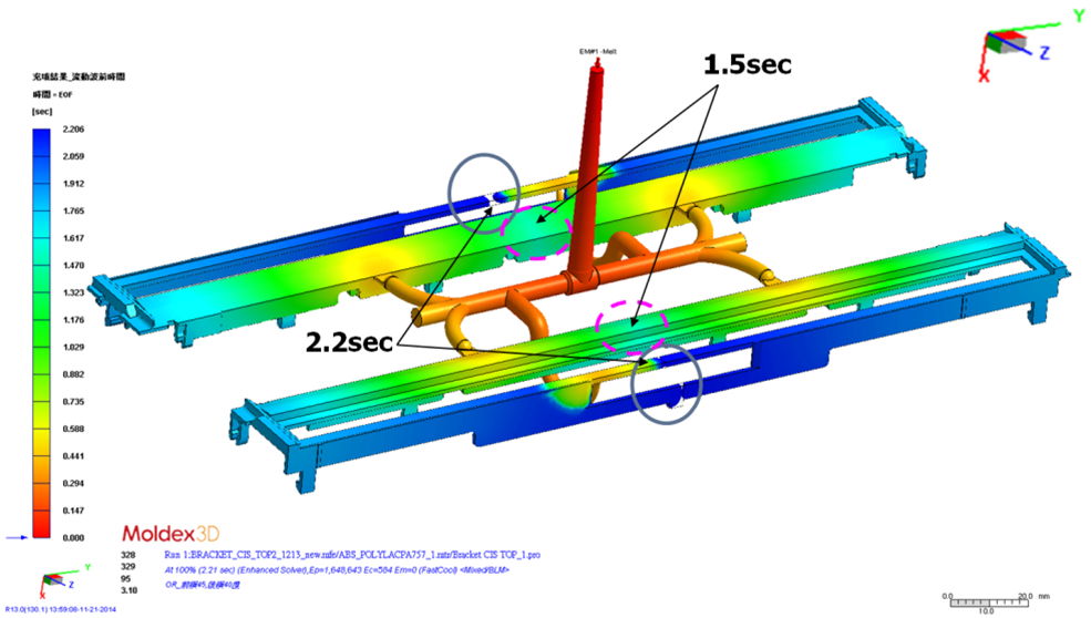 Fig. 2 The flow front of original design at 99.9% of the filling stage
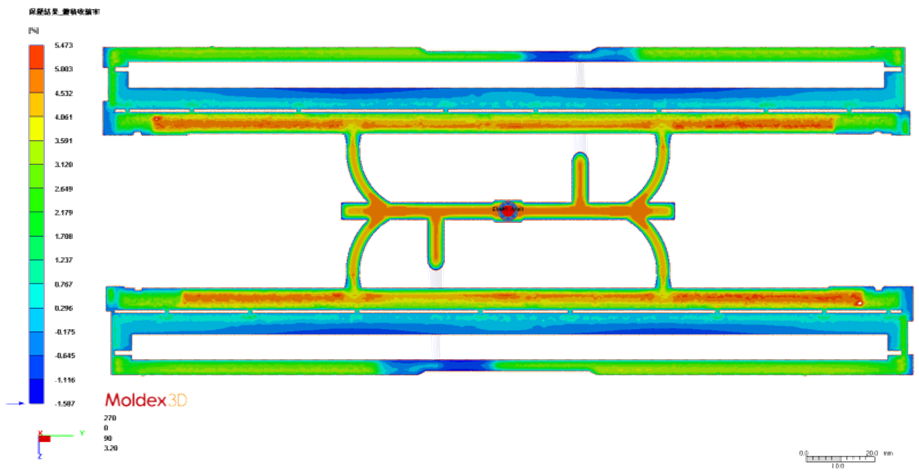 Fig. 3 The volumetric shrinkage for the cross section of this original design
In order to minimize flow imbalances and improve warpage, Lite-On Technology changed the gate locations and removed the center gates as shown in Fig. 4. The outer gates were moved 40 mm outward from the original locations. According to Moldex3D simulation results in Fig. 5, the revised design was able to effectively diminish the warpage displacement significantly.
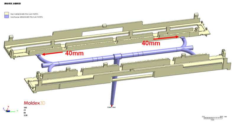 Fig. 4 The model of the revised design
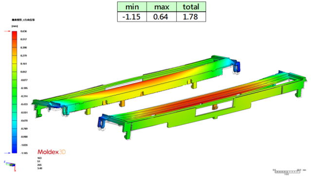 Fig. 5 The X-axis deformation of the revised design
Lite-On Technology conducted experiments to validate the simulation results. In Fig. 6, the analysis results of the original design show prominent deformation. On the contrary, in the revised design shown in Fig. 7, there is no obvious high shrinkage area; the warpage can be lessened greatly. Based on the above verification, Moldex3D simulation results are in a good agreement with the results from the actual mold trial.
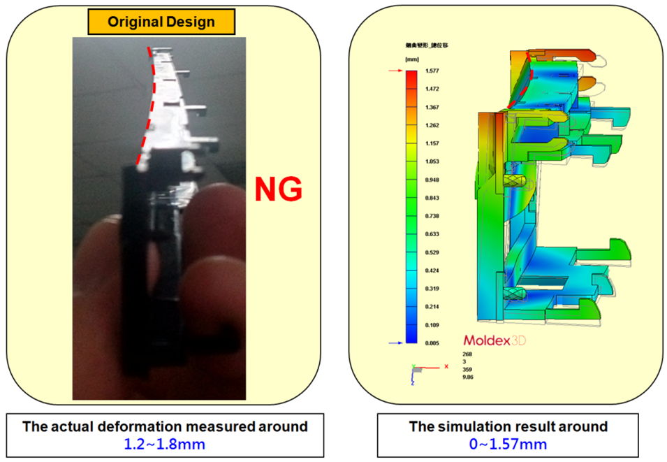 Fig. 6 The actual deformation measured and the simulation result of Moldex3D for the original design
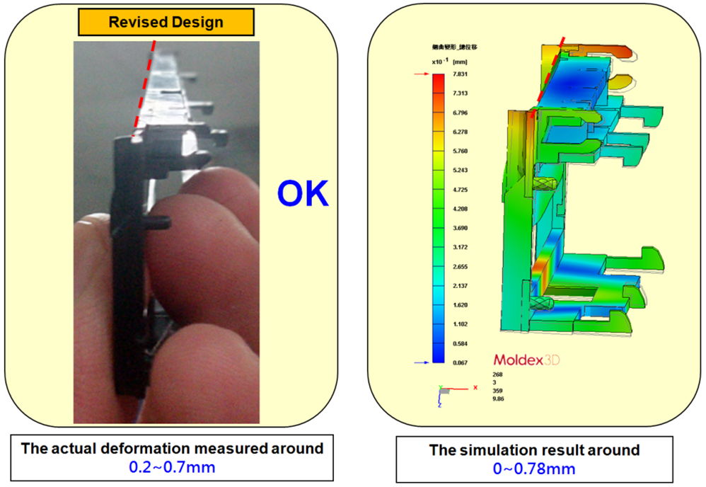 Fig. 7 The actual deformation measured and the simulation result of Moldex3D for the revised design
Moldex3D allows users to map the simulation data onto structural analysis models to simulate the effects of mounting a part during an assembly operation. Lite-On Technology carried out the structural analysis through LS-DYNA. Thus, the assembly-induced deformation and stress can be considered in the linear elastic analysis in LS-DYNA as shown in Fig. 8. The deformation of CIS Holder can lead to compression forces on the glass part, so the large deformation can make the glass part separate from the CIS Holder. In addition, the glass part of the revised design requires approximately 75% less stress than that of the original design.
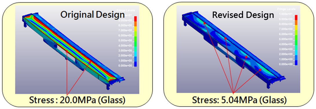 Fig. 8 Stress variation in assembly position after the glass part is mounted on the CIS holder
Results
With the integration of Moldex3D and LS-DYNA, the warpage of the part alone or the warpage of the assembly can be predicted. With Moldex3D FEA Interface, the users can export the process-induced fiber orientation, thermo-mechanical properties and residual stress data from Moldex3D to LS-DYNA for more realistic structural analysis. Moldex3D helps ensure that structural analysis can fully consider process-induced material properties. As a result, the integration of Moldex3D injection molding simulation and LS-DYNA structural analysis helps Lite-On produce quality parts in a cost-effective manner. This also gives Lite-On Technology greater confidence in plastic part design and manufacturing.