

Edited by Barton Lin, Chief Engineer at Technical Support Team, Moldex3D

- Customer: Stanley Engineered Fastening
- Country: U. S. A
- Industry: Automotive
- Solution: Moldex3D Advanced Package; Flow, Designer BLM
For more than 40 years, STANLEY Engineered Fastening has been revolutionizing fastening and assembly technologies for a variety of industries. In addition to developing fasteners that uniquely resolve assembly issues, STANLEY Engineered Fastening also provides extremely cost-effective tooling and installation processes. (Source)
Executive Summary
Typically, fastener designs are smaller in size, and controlling manufacturing variation is simplified. However, when larger and more complex parts are required, the team needs a tool that can help predict variations to overcome molding defects, such as warpage and short shots, in the injection molding process. In this case, the team was tasked with producing an optimum gating system for the protector part.
Challenges
- To determine valve gate location for optimal performance
- Avoid short shots
Solutions
STANLEY Engineered Fastening used Moldex3D to analyze design iterations at the earliest stages of product development. Through the simulation results, the team was able to determine the optimal number of valve gates and also the proper gate locations for the part. Moldex3D also helped the team in optimizing the cold runner system design, which not only saved money spent on valve gates but also achieved balanced filling.
Benefits
- Identified optimal gate locations during the initial tool design
- Reduced rework cost and stayed on schedule
- Eliminated short shots
Case Study
Based on the best practice of tool design, there should be a gate every 120 mm to ensure proper flow. Initially, STANLEY Engineered Fastening selected three valve gates, but they needed to determine their locations for optimal performance. During the plastic injection molding, the filling process is very critical. Short shot occurs if the proper gating locations are not selected. To overcome this issue, the STANLEY team used Moldex3D to verify the gate contribution and adjusted the gate locations accordingly.
After running a few iterations with Moldex3D, the team decided the optimal number of valve gates (3) and the optimal gating locations as shown in Fig. 1 & 2.
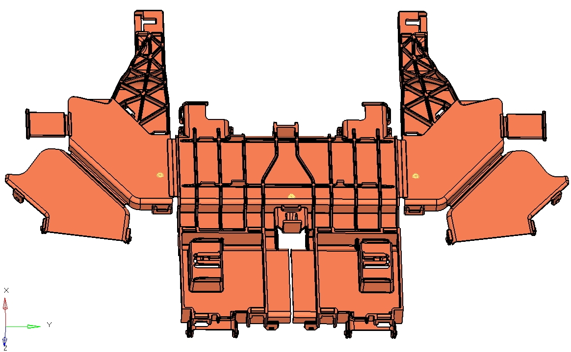
Fig. 1 Initial gate system (valve gates)
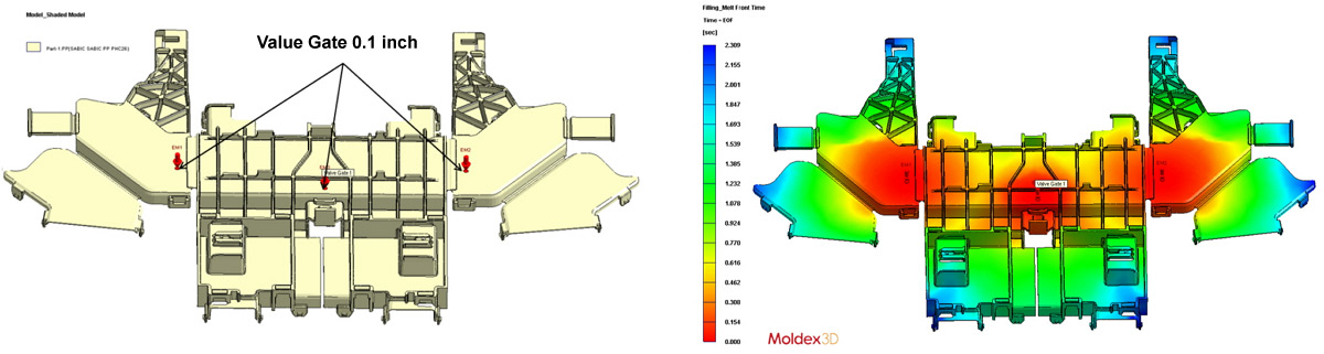
Fig. 2 Initial gate system (valve gates) and the result of melt front time
Due to the high cost of valve gates, the customer requested a more economical solution. Thus, the STANLEY team tried to find a runner system with a more balanced flow with the help of Moldex3D. Fig. 3 shows that the distance from the sprue entrance to Gate 2 is much shorter compared to Gate 1 & 3. Therefore, they designed a runner system in such a way that the plastic melt will enter the mold from the three gates simultaneously. The melt front simulation results of the optimized gate system are shown in Fig. 4.
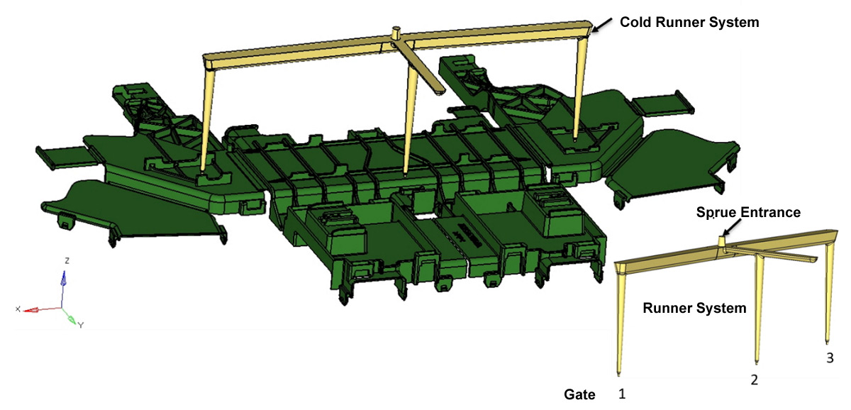
Fig. 3 The optimal gate system (cold runner)
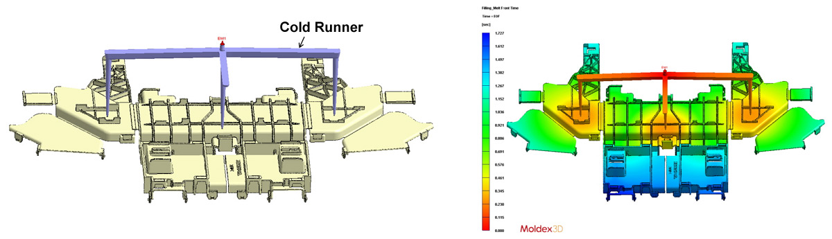
Fig. 4 Optimal gate system (cold runner) and the result of melt front time
Fig. 5 shows the filling patterns with three valve gates. (Material data: PP- SABIC PP PHC26 (MFI = 8g/10min)). Fig. 6 shows the filling patterns with a cold runner system. This tool design allowed the three gates to operate very similarly with a direct three-gate system (Material data: PP – TAIRIPROK4535 (MFI = 35g/10min)). As a result, the team made a small design change to the part by adding a rib near the gate location. This rib allowed the part to be filled faster.
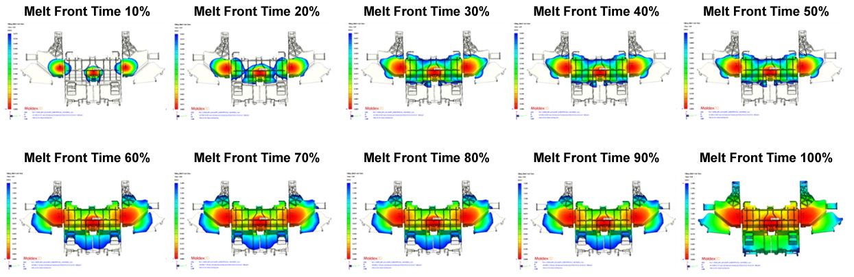
Fig. 5 The simulation results of the melt front time (with valve gates)
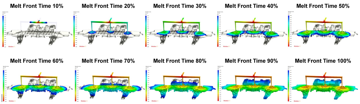
Fig. 6 The simulation results of the melt front time (with a cold runner system)
Results
Moldex3D predictions helped STANLEY attain the optimal gate system with no filling issues and minimal warpage with the cold runner system, eliminating the need for costly tool tuning or rework. Lastly, STANLEY was able to complete the project on time to meet customer’s expectations.