

- Customer: LMT Mercer Group, Inc.
- Country: USA
- Industry: Consumer Products
- Solution: Moldex3D eDesign
- View PDF Version
(Source: https://lmtproducts.com/)
Executive Summary
Two lighting parts, made from the same material, were both produced in the same mold to reduce the costs. However, their sizes were quite different, so unbalanced filling occurred. Through Moldex3D, the other issues, such as sudden spike in clamping tonnage and overworked cooling channels could also be detected. Therefore, optimization on runner/gate and cooling systems were made that resulted in the eliminations of unbalanced filling and sudden tonnage spike, the reductions of both clamping force and cooling time, and the improvements of both cooling efficiency and part flatness. In addition, substantial time and cost savings could be achieved too.
Challenges
- To complete the filling process at the same time for both parts
- To ensure the runner/gate configuration and cooling channel sizes and locations that would not cause excessive warpage on the parts
Solutions
Moldex3D provides the analyses for filling, packing, cooling, and warpage in which the effects of any design changes and modifications in runner/gate and cooling systems on the improvements on filling time, cycle time, cooling efficiency, and part flatness can be observed beforehand.
Benefits
- Succeeded in reducing the clamping tonnage required at the end of packing from 225 ton to 175 ton which reduces costs of the part too due to smaller press size required
- Succeeded in having both parts to be fully filled at 1.28 s; the initial runner and gate design resulted in full filing times of 1.07 s and 1.28 s for the smaller and larger parts, respectively
- Obtained optimized cooling channel design which reduced cycle time through reduced maximum cooling time by 11.99% and made the cooling efficiency difference only 13.759% from 25.452%
- Improved flatness of the smaller part by 2.56% and of the larger part by 6.18%
- Earned total savings of $11,500 for mold work and sampling charges
Case Study
The objectives are to reduce the cost of parts by both reducing the press size required through optimized runner/gate and reducing the cycle time, to keep part flatness within acceptable quality limits, and to accomplish all these goals before the making of the mold so that the tooling and sampling costs could be reduced.
Moldex3D eDesign was utilized to mesh the model which contains two different cavities in one mold; the smaller part was for LED board holder, whereas the larger one was for light reflector. Moldex3D became a powerful tool to detect and identify unbalanced filling through melt front time, sudden spike in tonnage of the clamping force, maximum cooling time, overworked cooling lines, and the Y-displacement for both parts.
The changes include runner layout and cooling system as illustrated and explained in Fig. 1 and Fig. 2.
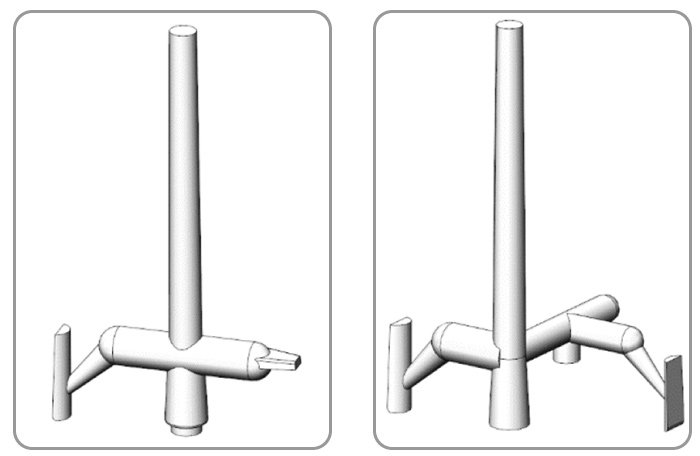 Fig. 1 The original design has the edge gate for the smaller part and jump gate for the larger part (left), while the revised design keeps the jump gate for the larger part but uses the extended jump gate for the smaller part (right).
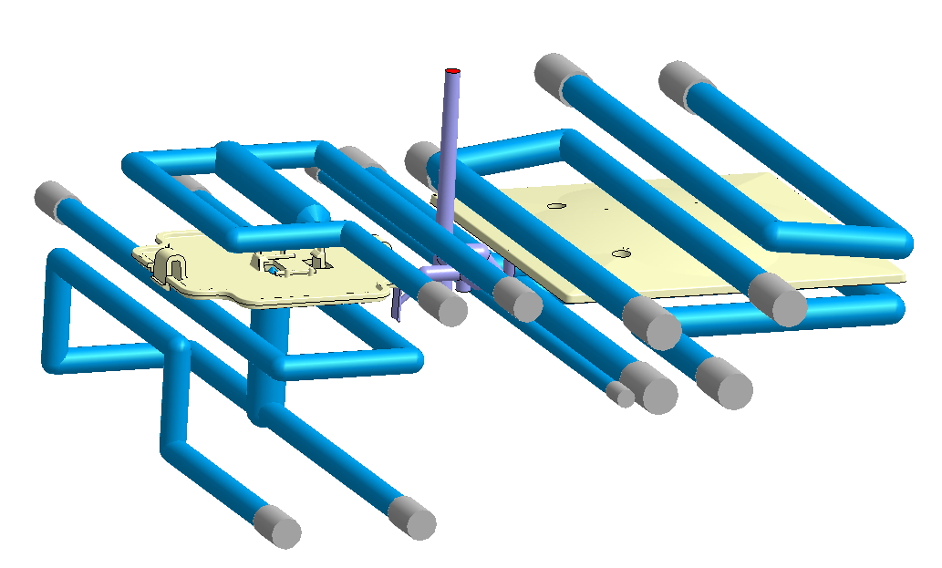
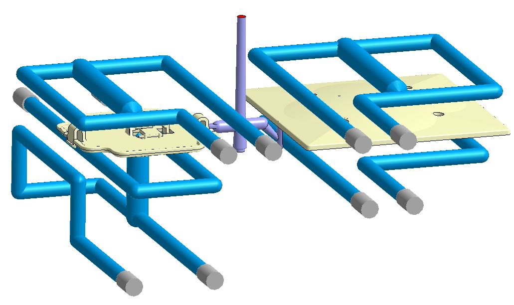
Fig. 2 Different from the original design (left), the revised design (right) splits the connected loop cooling channel for the larger part’s top and bottom sides and add a cooling channel for the larger part’s bottom side.
As shown by Moldex3D’s simulation results, the smaller part has been fully filled too early compared to the larger part. The revised design makes the flow path for the smaller part longer from its runner and gate design, so its filling time can catch up with the longer filling time of the larger part (Fig. 3).
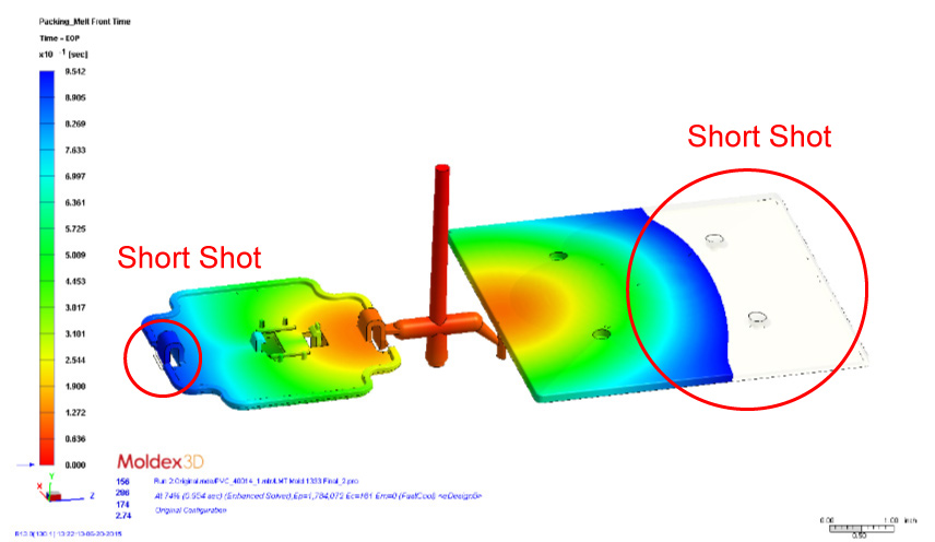
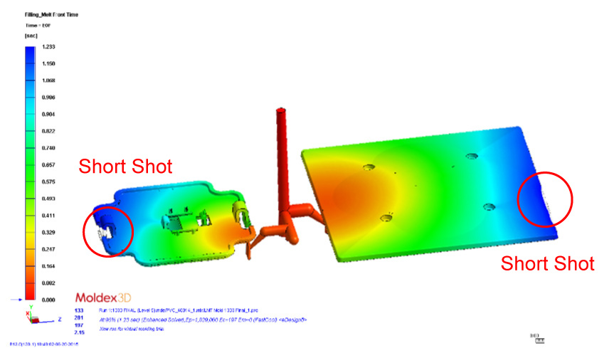
Fig. 3 The comparison between the melt front time of the original design at 74% filling (top) and the revised design at 96% filling (bottom) shows that the unbalanced filling for both cavities has been solved.
The next result is the cooling time in which the maximum cooling time can be reduced from 21.009 s to 18.489 s via optimized cooling system design. In other words, the cycle time could be reduced as well. The last result is the Y-displacement which represents the part flatness. The original design results in maximum displacements of 0.1981 mm and 0.6985 mm for smaller and larger parts, respectively. Meanwhile, the revised design can reduce the maximum displacements for both smaller and larger parts to 0.1930 mm and 0.6561 mm, successively.
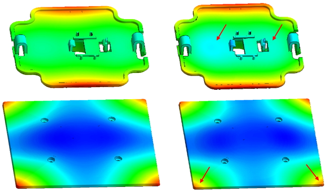
Fig. 4 The distributions of the Y-displacement for both of the smaller and the larger part show that the original design (left) has larger displacement than the revised one (right).
The design revision was verified by the actual injection molded parts. During initial mold sampling, the process conditions from Moldex3D were given to the process engineer. The process engineer made short-shot parts just before the end of the filling. The injection molded short-shot parts has identical short shot locations to the ones in simulation results as shown in Fig. 5.
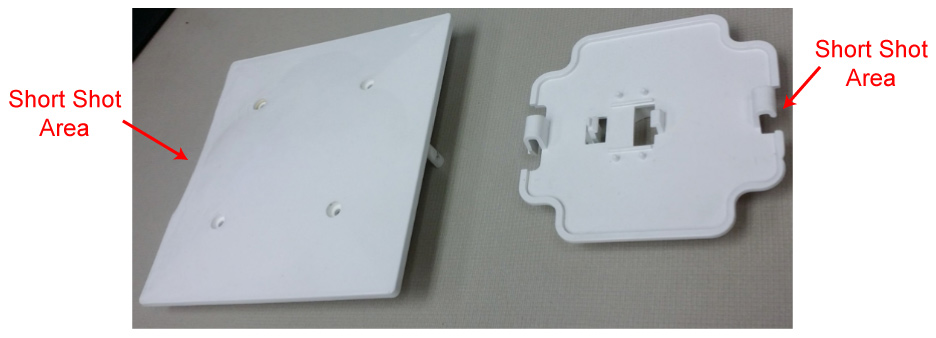
Fig. 5 The actual injection molded parts for the revised design for larger part (left) and smaller part (right) have identical short shot locations with the simulation result in Fig. 3.
Results
This project was a success in which the objectives of both reducing the part cost and improving the quality of the finished products had been accomplished. The design revision was made by modifying the runner/gate design and optimizing the cooling channel layout before the mold steel was cut and shaped. With the ease of use that Moldex3D offers, various designs were tested quickly to find the best results without having to make expensive changes to the tooling after the fact. By improving the mold and part designs with the assistance of Moldex3D, time to market and tool sampling had been streamlined. Thus, substantial time and cost savings could be achieved as well. Besides, the validation comparing the simulation result with actual injection molded parts showed that both filling results were very identical.