Moldex3D MuCell® supports solid mesh projects only. The procedures in the pre-processing stage are similar to those for basic modules. Follow the steps listed below to set up your first core-back simulation.
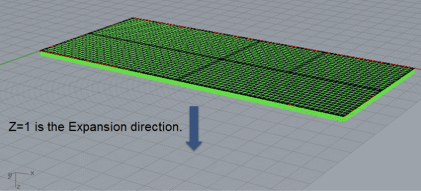
To run a core-back analysis, users can construct their geometry model with Moldex3D Mesh. The definition of the Moving Surface needs to be specified after the model mesh is built. In this example, we defined the direction of the moving surface as z=1.
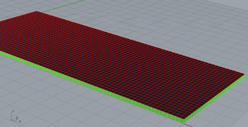
Select the moving surface as indicated by the red colored mesh, and click the down-right corner of BCsicon ![]() . When icon
. When icon ![]() pops out, choose
pops out, choose ![]() .
.
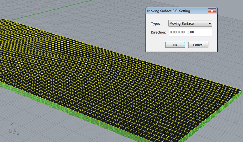
When the Moving Surface B. C. Setting dialogue pops out, users should define the direction as “0.00 0.00 -1.00”. This setting means the moving side of the mold (moving surface) will be pre-closed in the z=-1 direction, then expanded in z=1 direction.
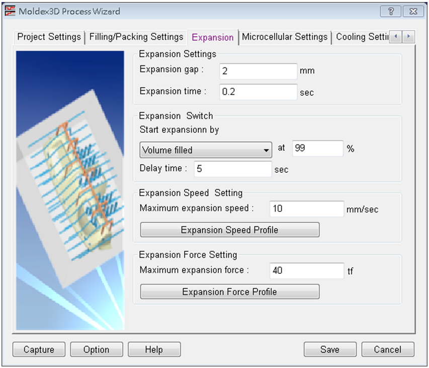
Expansion Settings parameters are Expansion gap and Expansion time, which are calculated according to the molding process.
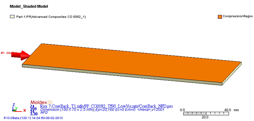
Once the imported mesh file (*.mfe) includes the definition of the moving surface, the Compression Region, as shown in orange, and will appear in the project.