Insert molding is a highly efficient process, through which metal stampings, bushings, electromechanical parts, filtration materials, and other discrete parts can be assembled into a single product. Moldex3D’s pre-processor tool provides a powerful capability which enables an automatic mesh generation and creates a proper mesh of the part, part insert, and other molding components for insert molding.
Now, Moldex3D R14 is able to support the analysis of the non-matching mesh between the part and part insert. However, to ensure high-accuracy analysis results, the mesh elements on the contact faces between the part and part insert must be matched. Moldex3D Designer BLM provides a feature to stitch them automatically so that users do not have to match them manually. As a result, users can save lots of time in the meshing process. The following steps show how to deal with a non-matching mesh.
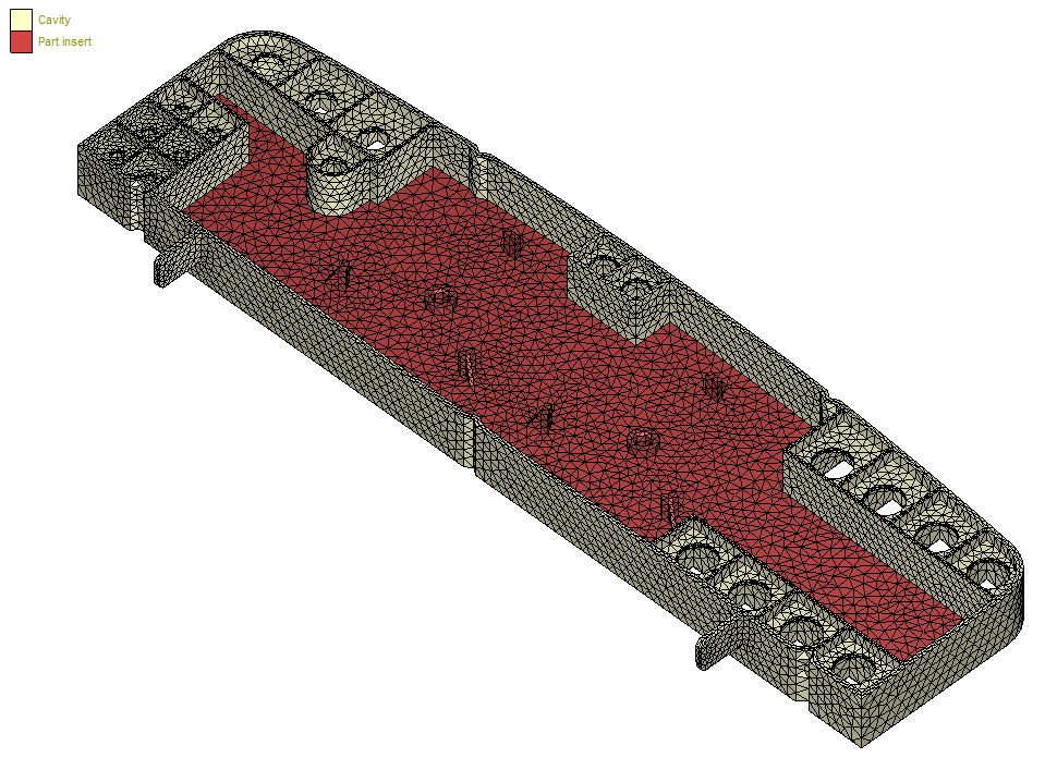
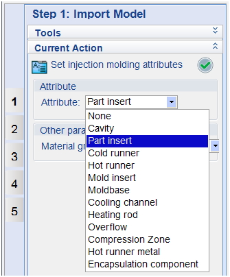
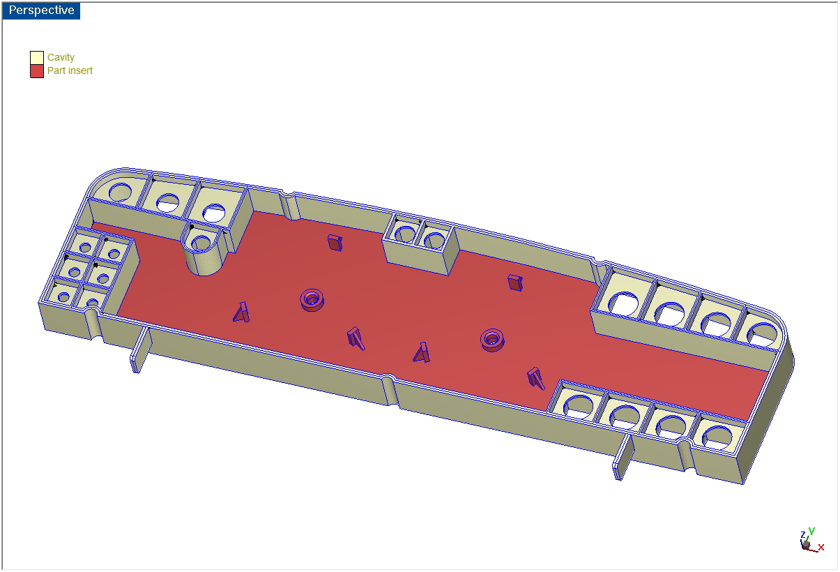
Step 1: Import the cavity and part insert into Designer BLM. Double click on the component to edit its attribute (the cavity is in yellow; the part insert is in red). In Step 2 and Step 3, prepare the MCM model with its runner and cooling system, similar to that for conventional injection molding (IM). In Step 4, specify the node seeding and BLM parameters prior to the mesh generation.
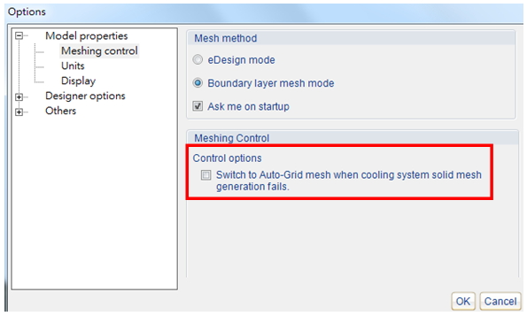
Step 2: Make sure to uncheck the option Switch to Auto-Grid mesh when cooling system solid mesh generation failsunder Model properties in Options Thus, Designer BLM will ensure the mesh elements on the contact faces between the part and part insert to be fully matched during the mesh generation.
Step 3: Click ![]() to start mesh generation. Next, Match contact faces feature will automatically match the mesh elements on the contact faces.
to start mesh generation. Next, Match contact faces feature will automatically match the mesh elements on the contact faces.
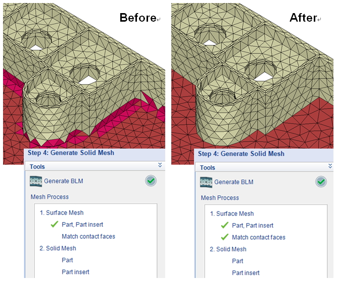
Note: If there are no critical defects found by the program or pause point set by the users, the whole meshing process will be automatically done by one click on Generate. All non-matching mesh elements are displayed in different color to make it easy to identify them before and after they are matched.
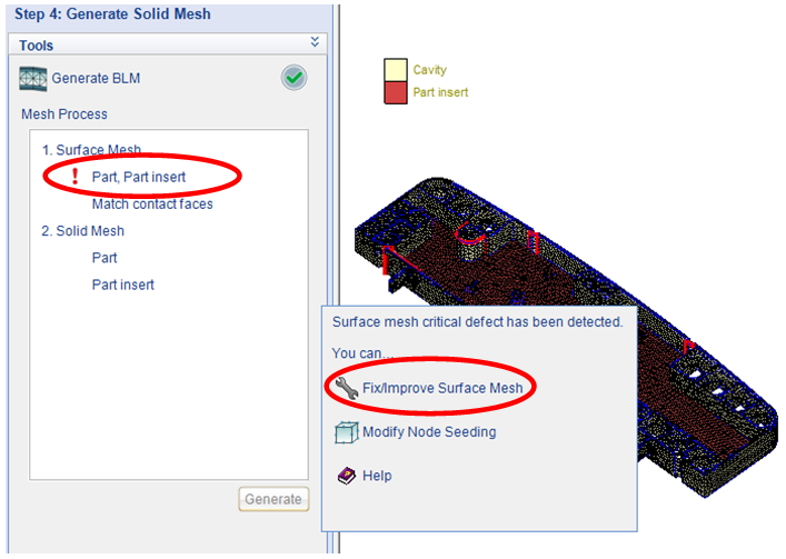
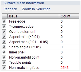
Note: If there are any critical defects detected in the surface mesh, the program will ask if the users want to use the tools in Fix/Improve Surface Mesh to fix them. Non-matching face issue can also be checked in the surface mesh information, but users can choose to leave it to the next meshing stage. After all of the critical defects have been fixed, click Generate again to continue the meshing process.
Step 4: Once the contact faces are successfully matched, Step 4 can be completed with solid mesh generation for the part and part insert as shown below. Users can then export the mesh model in Step 5 for further analysis application.