

- Customer: Plazology
- Country: UK
- Industry: Consultancy
- Solution: Moldex3D eDesign
- View PDF Version
Established in 2009 with the initial intention to supply injection mold tools globally, Plazology has expanded its services due to customers’ requests. Plazology now take on full projects from part design to production roll out. As an experienced and dynamic company, Plazology strives to stay in touch with the latest technology within the Plastics Industry, applying their knowledge and experiences (subject to non-disclosure agreements) to the market/area of interest of our customers. This enables Plazology to support numerous customers to produce plastic components with high quality, good consistency and cost efficiency.
Over the years, Plazology has built up excellent relationships with various organizations; this includes Universities both in the UK and overseas. (Source: www.plazology.co.uk)
This article is adapted from Injection World magazine, October 2014. ©Applied Market Information Ltd. 2014.
Executive Summary
In order to produce good quality injection molded parts with high consistency, a well-designed part and mold along with the right material and processing parameters is critical. Changes made to any of the mentioned four factors can have a significantly effect on the molded part. Without having true understanding of the polymer behavior inside the mold, more often than not, engineers tend to “process the part dimensions in”. This leads to small processing window – slight change in process can cause the part dimensions to fall out of specification limit. The trial and error method is laborious, expensive and ineffective, making it infeasible to be conducted in today’s fast moving industry.
Plazology, a leading company for injection molding technical consultancy based in United Kingdom, is seeing a big push in molding simulation, which is able to predict how parts behaves inside the mold and post molded phenomenon. According to Jasmin Wong, Project Engineer at Plazology, “Traditionally, customers look to prototype molds before commencing with large volume production molds. However, this adds cost and lead-time to the program,” Jasmin points out. “Using simulation is an element where we can look to gain great confidence that the parts are designed correctly for molding and the tools are designed with optimized cooling and gate positions.”
Plazology implemented Moldex3D because it helps them design faster with greater confidence. “Moldex3D has provided us with additional confidence in our own internal decision making,“ Jasmin stresses. “Not only do we use Moldex3D for full analysis work before building the actual tool, we can use it to troubleshoot current production quality issues too. This has aided our customers’ toolmakers who don’t have easy access to molding simulation, helping them to optimize their molds, cooling layouts and reducing cycle times.”
Challenges
- Warpage
- Concentricity
Solutions
Use Moldex3D DOE module to determine the optimum process settings to improve warpage and linear shrinkage.
Cast Study
The following case study illustrates how Plazology utilizes Moldex3D plastic injection molding simulation software to attain optimum process settings.
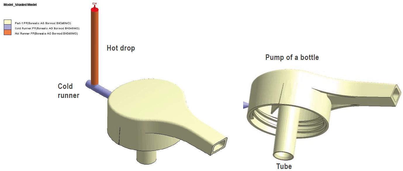 Fig. 1 CAD model of a hand dispensing pump used in this case study
The above (Figure 1) is a hand dispensing pump of a sanitizer bottle. In this case study, the main area of concern for this model is the warpage as well as the concentricity of the tube, as it affects the fit and functionality of the pump. As the part has very tight tolerance, knowing the optimum process condition is required to keep warpage at the minimum and concentricity as circular as possible.
Plazology first carried out a preliminary Fill, Pack, Cool and Warp analysis to ensure that the part has no filling difficulty such as short shot or hesitation. DOE was then carried out. Since the area of concern is the warpage and concentricity, these two will be the quality factor/response used in this DOE. Four control factors that will affect warpage and concentricity will be used to carry out the DOE. In this case, melt temperature, packing pressure, cooling time and fill time was used. Taguchi L9 DOE was then conducted. (Note: Taguchi DOE assumes no significant interaction between factors which may not necessary be true. The reason why Taguchi was chosen in this case study is to find out the relationship between the factors and response using shortened simulation time.)
The Taguchi L9 DOE design can be seen in the Table 1.
| No. | Control Factor | Level 1 (Low) | Level 2 (Original) | Level 3 (High) |
| 1 | Melt Temperature (°C) | 225 | 235 | 245 |
| 2 | Packing Pressure (MPa) | 9 | 12 | 15 |
| 3 | Cooling Time (sec) | 8 | 10.6 | 12 |
| 4 | Filling Time (sec) | 0.1 | 0.2 | 0.3 |
Table 1 Taguchi L9 DOE design used in this case study
Table 2 shows the process setting of the 9 runs using Taguchi L9 Design. Moldex3D DOE then uses mathematical calculations based on user’s specification (minimum warpage and linear shrinkage between nodes – used to measure concentricity which will be explained later in the article) to determine the optimum process setting, reflected as Run 10.
| Run No. | Melt Temperature (°C) | Pack Pressure (MPa) | Cool Time (sec) | Fill Time (sec) |
| 1 | 225 | 9 | 8 | 0.1 |
| 2 | 225 | 12 | 10.6 | 0.2 |
| 3 | 225 | 15 | 12 | 0.3 |
| 4 | 235 | 9 | 10.6 | 0.3 |
| 5 | 235 | 12 | 12 | 0.1 |
| 6 | 235 | 15 | 8 | 0.2 |
| 7 | 245 | 9 | 12 | 0.2 |
| 8 | 245 | 12 | 8 | 0.3 |
| 9 | 245 | 15 | 10.6 | 0.1 |
| 10 | 225 | 15 | 12 | 0.1 |
Note: Run 10 (optimized run) will be further explained under conclusion.
Table 2. Process setting of the Taguchi L9 runs
Warpage (Total displacement – mm)
From the 9 different runs, a main effect graph for warpage is plotted as seen in Figure 2.
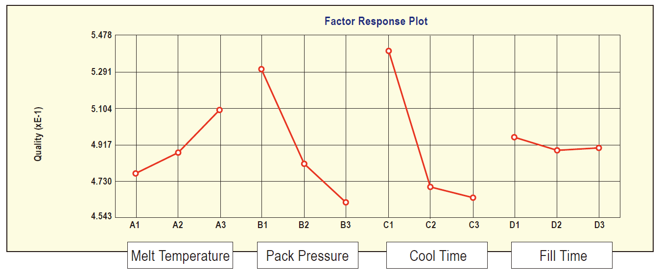 Fig. 2 Main effect plot for part warpage
From Figure 2, it can tell that by increasing the pack pressure and cool time, warpage is reduced. Increasing melt temperature on the other hand, leads to higher warpage. Using fill time of 0.2 sec or 0.3 seconds seems to have slightly lesser warpage than 0.1 sec. Hence, we know that in order to achieve lower warpage, the optimum process setting should be melt temperature – 225°C, pack pressure – 15MPa, cool time – 12 sec and fill time –0.3 sec.
From the results obtained in Moldex3D, Plazology then make use of Minitab 17 (statistical software), to find out which of the four factors has the biggest influence in the part warpage. Based on the table in Figure 3, cool time which is ranked 1 has the biggest impact on part warpage, followed by pack pressure, melt temperature and lastly the fill time.
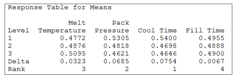 Fig. 3 Response table for means (warpage)
The area graph seen in Figure 4 also shows a quick comparison of the 9 different runs against warpage. Run number 3 seems to give lesser warpage as compared to the rest of the 8 runs.
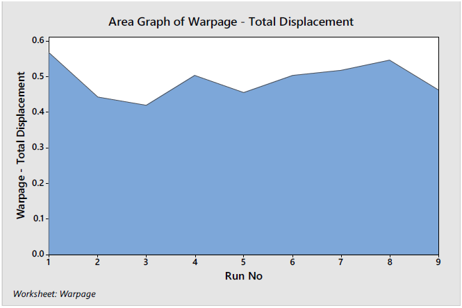 Fig. 4 Area graph of part warpage (total displacement)
Concentricity (Linear shrinkage between nodes – %)
Concentricity is difficult to be measured, in real life or in simulation. In real life, distance between different points is measured using the coordinate-measuring machine (CMM). In Moldex3D, the linear shrinkage between different nodes is measured (see Figure 5 below). Eight different nodes were identified. The linear shrinkage of the diameter of the tube across A, B, C and D is measured. The lower the linear shrinkage, the more circular or better concentricity the tube of the part has.
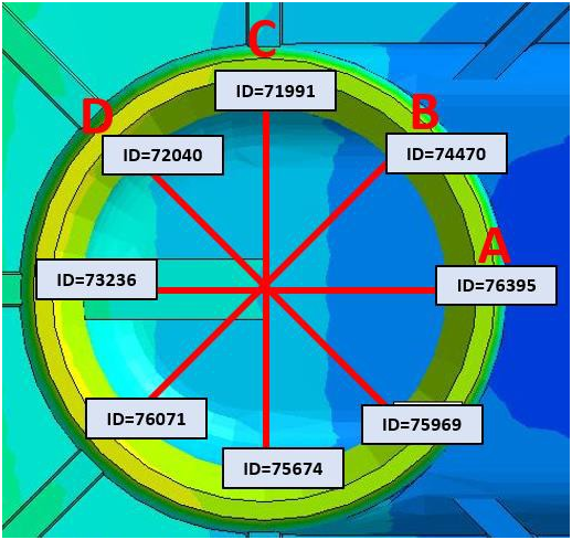 Fig. 5 Eight different nodes measured for linear shrinkage
The main effect plot for linear shrinkage can be seen below in Figure 6.
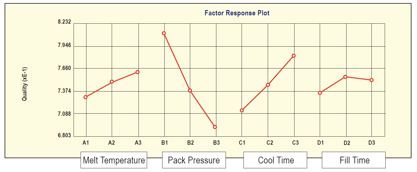 Fig. 6 Main effect plot for linear shrinkage between nodes (measure of concentricity)
From Figure 6, it can be seen that in order to get better concentricity/linear shrinkage between the nodes, a lower melting temperature, cooling time and filling time with a high pack pressure is preferable. Hence, we know that in order to achieve lower linear shrinkage, the optimum process setting should be melt temperature – 225°C, pack pressure – 15MPa, cool time – 8 sec and fill time – 0.1 sec. However, a cool time of 8 seconds might not be practical since it will give high warpage (as seen in Figure 3).
Likewise, Minitab is used to find out which of the four factors gives the greatest impact on linear shrinkage. Based on the table in Figure 7, pack pressure is ranked 1. This is followed by cool time, melt temperature and lastly the fill time.
Since 8 sec cool time will lead to high warpage, a compromise may sometimes have to be made. As mentioned earlier, for linear shrinkage, pack pressure is more of a contributing factor than the cool time. Hence, it makes more sense to use 12 sec cool time with 15MPa Pack pressure.
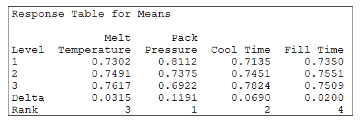 Fig. 7 Response table for means (Linear shrinkage)
Comparing the 9 different runs for linear shrinkage (see Figure 8), run 6 gives lower linear shrinkage as compared to the other 8 runs.
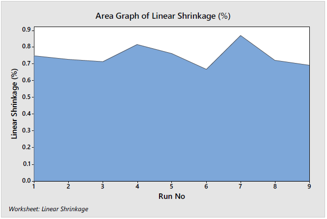 Fig. 8 Area graph of linear shrinkage between nodes (measure of concentricity)
Benefits
Based on user specification, Moldex3D uses mathematical calculations to obtain the optimized run (Run 10). For this case study, weighting for warpage was the same as the linear shrinkage. However, based on the results above, the optimum process setting for lowest warpage is to have cool time of 12 sec and fill time of 0.3 sec. Optimum process for lowest linear shrinkage, on the other hand, requires a cooling time of 8 sec and fill time of 0.1 sec. Thus, Moldex3D came out with a compromise process setting (melt temperature – 225°C, pack pressure – 15MPa, cool time – 12 sec and fill time – 0.1 sec), which is used as the optimum run.
From the area graphs seen in Figure 9, it shows that Run 10 (optimized run), gives the lowest warpage compared to the other 9 runs, while continue having low linear shrinkage.
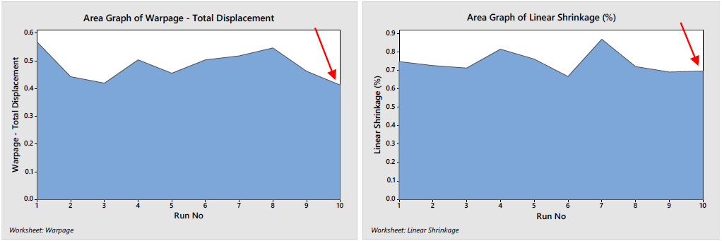 Fig. 9 Optimized run (Run 10) is compared with the other 9 runs.
From the DOE simulation results (see Figure 10 and 11), it tells that the part warpage and concentricity of the tube has been significantly improved. Warpage is seen to have improved by approximately 20-30% while keeping a low linear shrinkage to approximately 0.6-0.7%.
Before DOE DOE Optimised Run #10
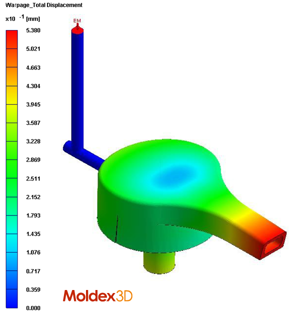
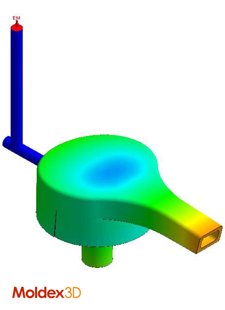
Fig. 10 Improvement in warpage (total displacement) is observed
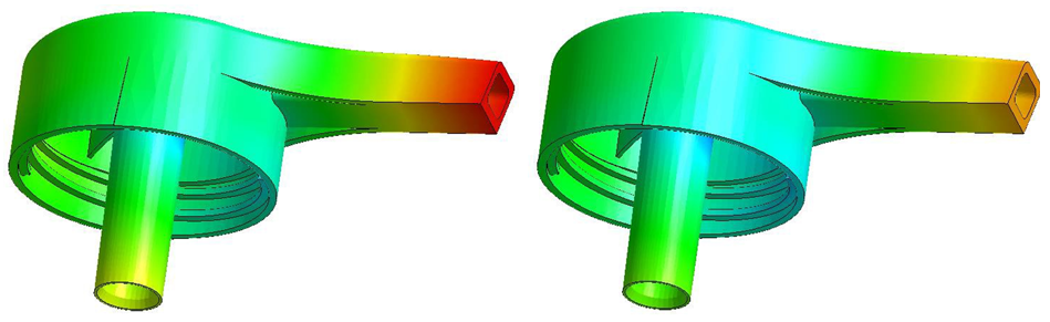 Fig. 11 Improvement in warpage of the tube is also observed
Based on the above case study, it is important that designers/molders understand that these numerical results in simulation is a relative comparison and should not be treated as an absolute value. This is because there are various uncontrollable factors in the actual mold floor which cannot be reenacted in simulation. However, with the aid of Moldex3D DOE, it gives designers a head start on which are the control factors that should be focused on and the relationship it has with part quality.
“We feel that Moldex3D has been fundamental in growing this side of our business due to the accurate and reliable results it has shown to give Plazology,” Jasmin says. “Not only that, Moldex3D enables our customers to work better and smarter with more confidence,” she adds.
 |
Moldex3D has provided us with additional confidence in our own internal decision making. Not only do we use Moldex3D for full analysis work before building the actual tool, we can use it to troubleshoot current production quality issues too.
Jasmin Wong, Project Engineer at Plazology |
About Jasmin Wong
Jasmin Wong is a Project Engineer for Plazology, based in UK. Plazology works alongside with various global leading companies in the plastic industry, across Europe and Asia. They specialize in Product Design Optimization Injection Mold Flow Simulation, Mold Design, Precision Mold Procurement and Management; and Mold and Process Validation. Jasmin has also recently been awarded the Moldex3D Analyst Certificate by S4innovation, which supplies Moldex3D software in the UK.
About s4 innovation
s4 innovation Ltd is a software and service provider focused on providing technology and professional services to the injection moulding manufacturing industry. They are committed to the delivered of world leading injection moulding simulation technology, Moldex3D, including training and consultancy to a large array of customer base helping them achieve accurate time to market and return on investment. More information about s4 innovation can be found at www.s4innovation.com.