

GOOD VIEW has more than 39 years of experience in providing high quality plastic manufacturing solutions from Product design and engineering, Project management, Tool making, Custom plastic molding, Decoration, Product assembly, Warehousing and Logistics.
Summary
The product in this study is a composite miter saw handle of an electric tool. Due to the material used (PC LEXAN BFL2015), the hardness is quite high. During production, two operators were required to trim the flash and another one to handle product retrieval and packaging, resulting in a heavy labor burden. Therefore, Good View aimed to reduce manual labor through optimizing runner designs and to lower production costs by adjusting molding conditions.
Challenges
- Adjusting molding parameters to reduce pressure loss after flash trimming.
- Meeting the requirement of part warpage after flash reduction in the runner.
- Reducing the injection molding cycle time of the product.
Solutions
By leveraging Moldex3D simulation, the Good View team quickly assessed and evaluated the impact of mold design on product deformation and shrinkage. The team utilized Moldex3D to modify runner designs — reducing the number of sub-runners and adjusting gate sizes — to arrive at the optimal design solution.
Benefits
- After flash reduction, part deformation met the requirement, achieving a 25% reduction in raw material costs.
- Adjusting molding parameters through simulation to reduce the number of mold tryouts.
- Reducing labor costs by 67% and as a result, lower production costs.
Case Study
The product in this case is a two-cavity mold, consisting of left and right parts, as shown in Figure 1.
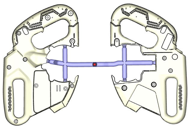
Fig. 1 A two-cavity mold.
The Good View team first utilized Moldex3D to validate the design. Figure 2 shows the melt front simulation result, which closely matches the actual molded part.
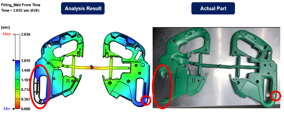
Fig. 2 The melt front simulation result and the actual part.
They then validated weld line positions. Figure 3 demonstrates that weld line positions on the actual part were consistent with the analysis results.
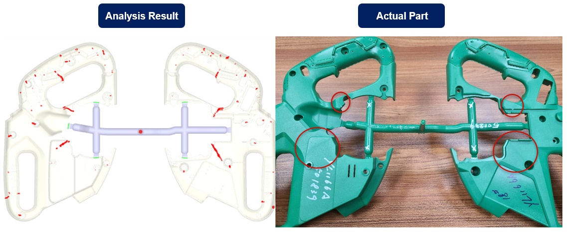
Fig. 3 Weld lines validation.
To ensure product quality, the team further validated overall deformation dimensions. As shown in Figure 4, the analysis result was close to the actual part as well.
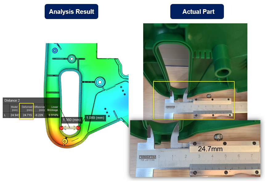
Fig. 4 Deformation validation.
Based on these simulation results, the team proceeded to adjust runner sizes and optimize molding parameters to identify the most suitable solution. With experience and Moldex3D, the team optimized the mold design mainly by modifying the runner system. In the optimized design, two sub-runners were removed, and both sub-runner and gate size were reduced, as shown in Figure 5.
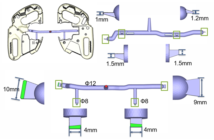
Fig. 5 Mold design optimization.
As shown in Figure 6, the optimized design exhibited a noticeable reduction in the number of weld lines. It also achieved better performance in weld line temperature (312 °C) and weld line meeting angle (125 °–141 °). Since the processing temperature of the material was 305 °C, it could be determined that weld lines did little harm to the appearance and the strength.
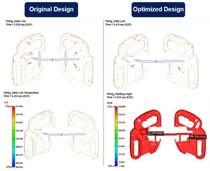
Fig. 6 Weld line comparison.
As shown in Figure 7, the original sprue pressure was 33.8 MPa, while the optimized sprue pressure was 43.6 MPa. Under actual molding conditions, the maximum injection pressure for both designs reached the upper limit; however, the parts could still be fully filled. The design change also allowed for appropriate reduction of injection speed.
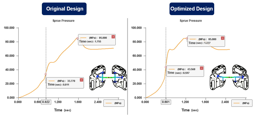
Fig. 7 Sprue pressure comparison.
As shown in Figure 8, the maximum clamping force of the original design was 383 tons. After design modification, it was 338 tons — a reduction of 45 tons. In addition, the cycle time was reduced from 14.3 secs to 12.6 secs.
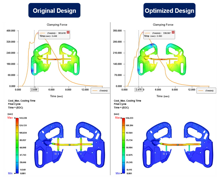
Fig. 8 The optimization of the clamping force and the cycle time.
The Good View team modified the mold design based on the warpage analysis result and verified key part dimensions. The result (Figure 9) showed minor variation between the original and optimized design, meeting the client’s requirements. After physical validation, the simulation result was consistent with the actual part (Figure 10.)
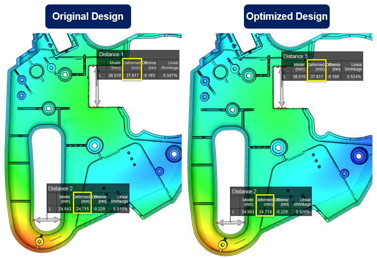
Fig. 9 Part dimension comparison.
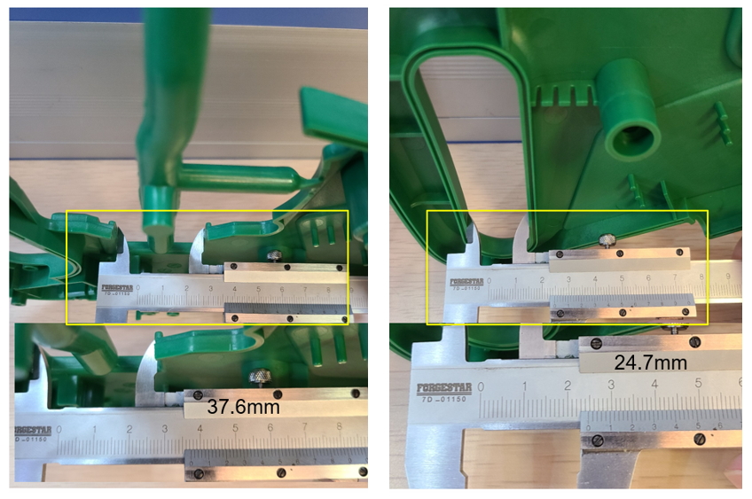
Fig. 10 The actual parts’ dimension comparison.
Figure 11 demonstrates that the mold tryout results were highly consistent with the melt front analysis results.
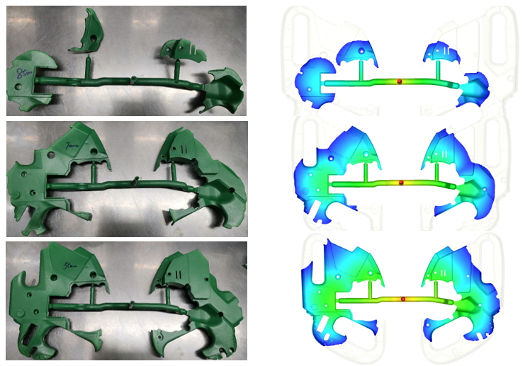
Fig. 11 Melt front comparison.
Conclusion
The Good View team used Moldex3D to optimize the composite miter saw handle and validated the accuracy of simulation. By comparing the original and modified design, the team was able to confirm the optimal solution and achieved:
- 25% reduction in raw material costs
- 67% reduction in labor costs
- lower clamping force
- shorter cycle time
After the mold tryout, the actual part closely matched the simulation results. In the end, they successfully met the client’s requirement of deformation, reduced the number of mold tryouts, and improved molding efficiency. This case study not only verifies Moldex3D’s value in cost optimization and design validation but also builds valuable experience for similar products, laying a foundation for future product development and production optimization.