When preparing a mesh for a Multi-Component Molding (MCM) model, Moldex3D Designer BLM supports the analysis of using non-matching mesh topology at the contact face between the part and the part insert, which is also known as the “Auto-Grid” feature. This feature helps users attain continuous analysis results across the whole model without manually adjusting/matching the mesh in the contact-face area. As a result, users can reduce a great deal of time and efforts spent on completing the meshing process. The following article will show a step-by-step process of generating an Auto-Grid mesh.
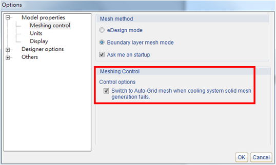
Step 1. Check Switch to Auto-Grid mesh when cooling system solid mesh generation fails, under Model properties in the Options toolbar. In this way, Designer BLM will automatically create an auto-grid mesh if it detects any non-matching mesh elements.
Note: This function can prevent failures in generating cooling system solid meshes due to non-matching mesh topology.
Step 2. Next, complete the solid mesh generation for the runner and cooling systems, following the general procedure for mesh generation in Designer BLM.
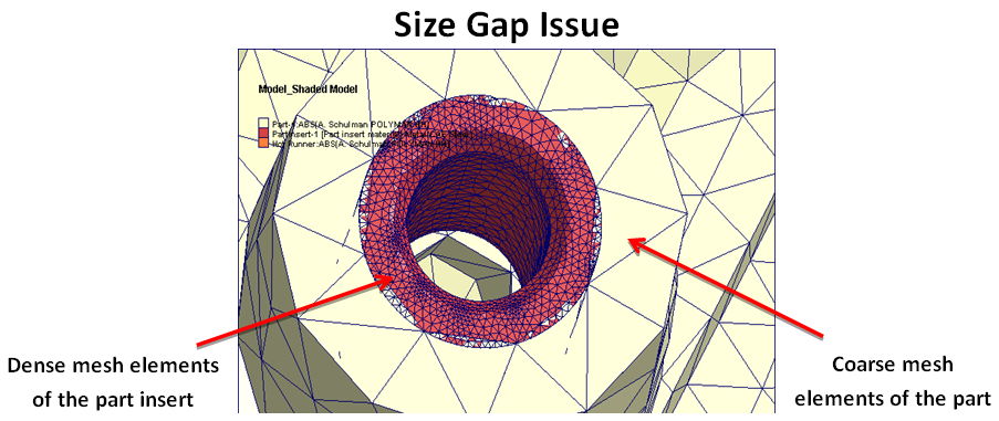
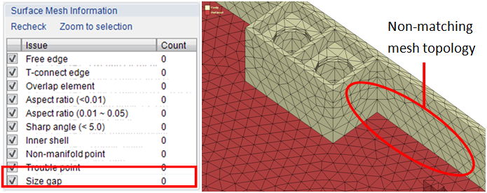
Note: Using Auto-Grid feature will keep the non-matching mesh elements, but it will automatically detect and record the mesh elements that show a significant size difference in the part and the part insert contact-face area in Surface Mesh Information.
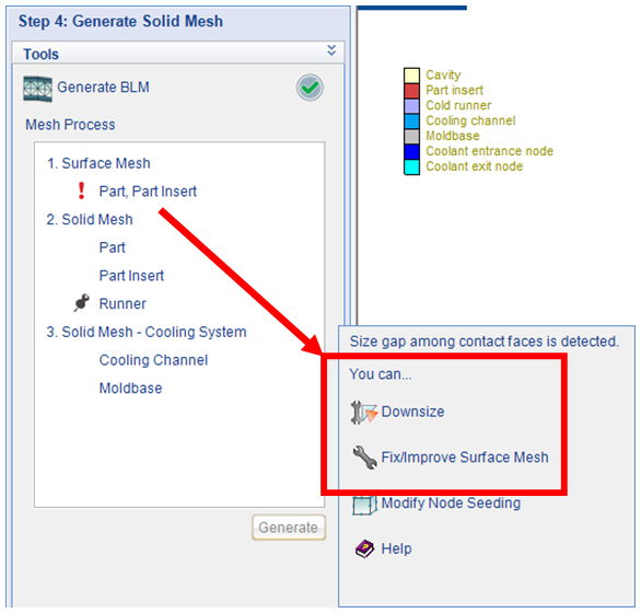
Note: If the size gap is severe, as shown in the example below, the Downsize wizard tool will appear and fix the issue automatically.