
The local fiber orientation is a key factor in determining the material behaviors of fiber reinforced plastic parts produced by injection molding. In order to obtain more accurate prediction of material properties of reinforced polymers, it is important to take into account process-induced microstructure in the early design phase. Moldex3D Digimat-RP provides capabilities to link injection molding simulation with structural analysis. The local fiber orientation analysis gained from Moldex3D simulation is used by Digimat-RP to compute the anisotropic nonlinear material properties in each element of the FE model.
Step 1: Output Moldex3D analysis results
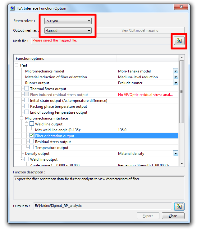
- To create the fiber orientation file (*.o2d) in Moldex3D, go to FEA Interface and specify Stress solver and select Mapped to output the mesh file.
- Click on Open
 to specify the FE mesh file for mapping (here we use *.k of LS-DYNA).
Note: For better mapping result, use View/Edit model mapping to check consistency between Moldex3D mesh and structural mesh. If they are not consistent, the mesh models have to be adjusted. - Check Fiber Orientation Output to create the *.o2d file and click Export.
Step 2: Import model and nonlinear material in Digimat-RP
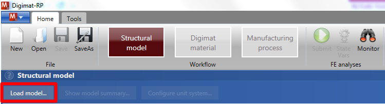
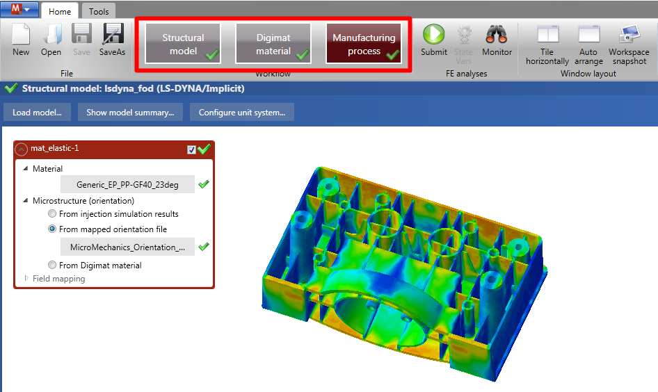
- Firstly, click on Load model in the Home ribbon to import your FE model.
Note: The FE model has to be a complete model including boundary conditions, applied loads and a material definition. For each section mentioned above, a Digimat material is desired. Digimat-RP will overwrite the original material definition with a Digimat User’s Material.
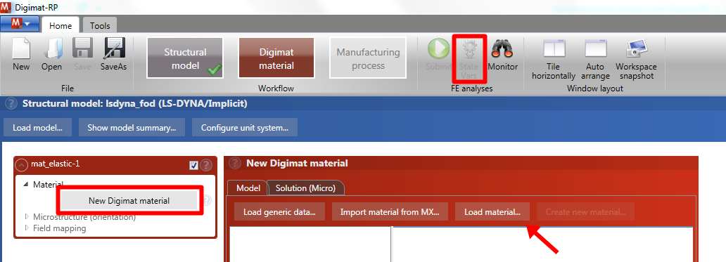
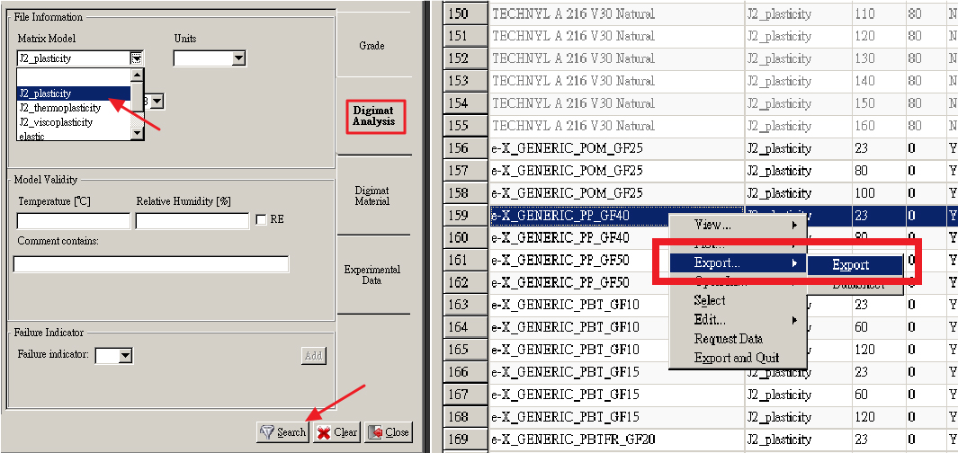
- Secondly, click on New Digimat Material and then Import material from MX. Choose a nonlinear model from Digimat-MX database. Right-click on it and then click Export.
Note: To quickly search for nonlinear material models, go to the tab Tools and use Advanced Filter (or press Ctrl + F). Click the Digimat Analysis tab in Advanced Filter, select J2_plasticity or J2_thermoplasticity, and then click on search for nonlinear material models.
Note: By clicking on State Vars , users can view all the state variables defined by the Digimat material which will be additionally output in the structural simulation.
Step 3: Import O2D file and submit the project
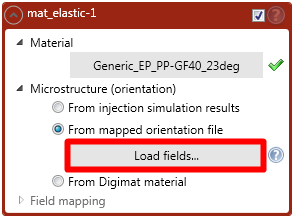
- After selecting the material model, click From mapped orientation file and then Load fields in the Digimat Material box to import the fiber orientation file (*.o2d) from Moldex3D Project.
Note: After importing the fiber orientation file, the green check marks for Material, Microstructure (orientation), field mapping can be seen in the Home ribbon. Now the coupled Digimat-RP analysis is completed.
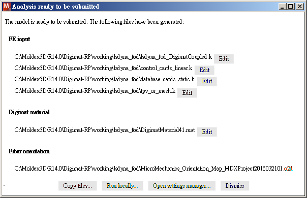
- Click on Submit
 to run the simulation. Choose a Project output directory and click Run locally in the next dialog. A new window will appear for users to select the number of CPU used for the computation. Click on Run to start the simulation.
Note: The adequate executable file for the desired FE solver has to be set. Go to Settings in the Tools ribbon and view the set executable file paths.
Step 4: Apply Digimat result in FEA
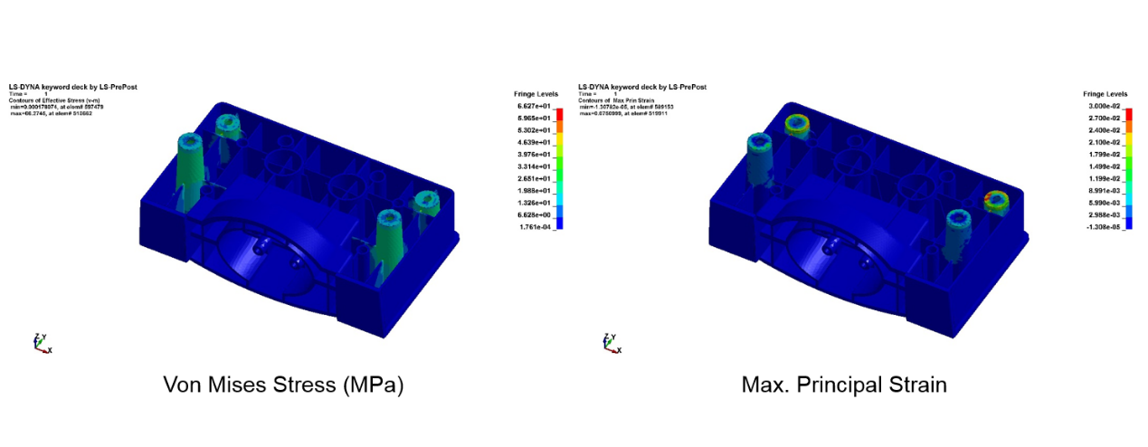
The progress of the simulation can be monitored in Digimat-RP. After the simulation is finished, the results can be opened with a post processing tool (here LS-PrePost).
- Employ the anisotropic nonlinear Digimat material model to predict the structural behaviors affected by the local fiber orientation.
- Plot additional micromechanical results of Digimat-RP for the constituents of the fiber reinforced polymer in the Post Processor
