Cindy Teng, Engineer at Technical Support Division of CoreTech System (Moldex3D)
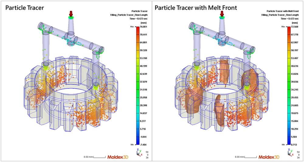
Moldex3D offers rich and intuitive visual indicators to help users better interpret analysis results. In previous versions, by releasing particles from the melt entrance at different times, Particle Tracer can display the current position and specific data (e.g. flow length, temperature) of each particle. Now, the Particle Tracer is further integrated with the Melt Front, providing a better demonstration of flow behavior.
Most results in Moldex3D are presented using color contours mapped onto the model while some direction-related results (e.g. Velocity Vector or Fiber Orientation) are visualized using segments. Results obtained from Particle Tracer are presented with points, however these visual elements may appear too dense or not clear enough, depending on the model, mesh, and even the display device. To address this issue, Moldex3D allows users to adjust the length, width and density of fibers and vectors — and now the size of the particle as well.
The following steps use Fiber Orientation results as an example to explain how to adjust the display settings.
Step 1
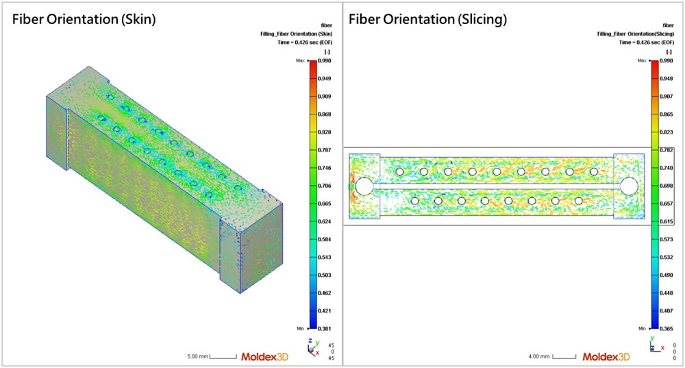
Run an analysis with the Fiber Orientation result in Moldex3D Studio using a fiber-reinforced material. In this project, after the melt enters the cavity from the gate, the Fiber Orientation (Skin) mainly aligns along the flow direction. Through the Fiber Orientation (displayed in slicing), the fiber arrangement inside the model can be further observed.
Step 2
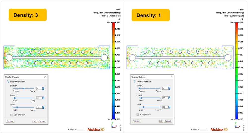
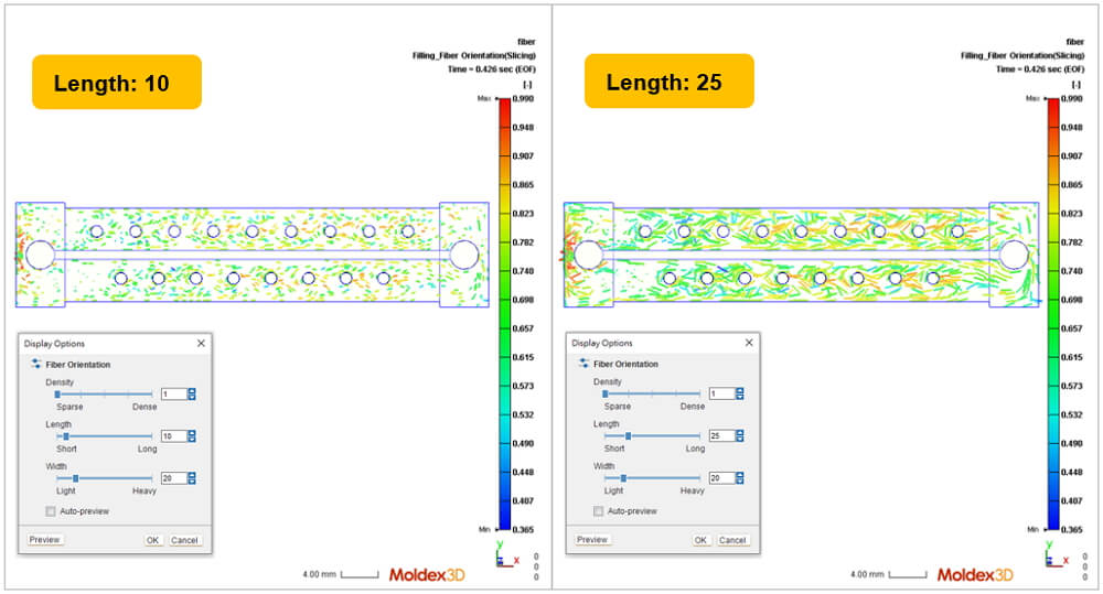
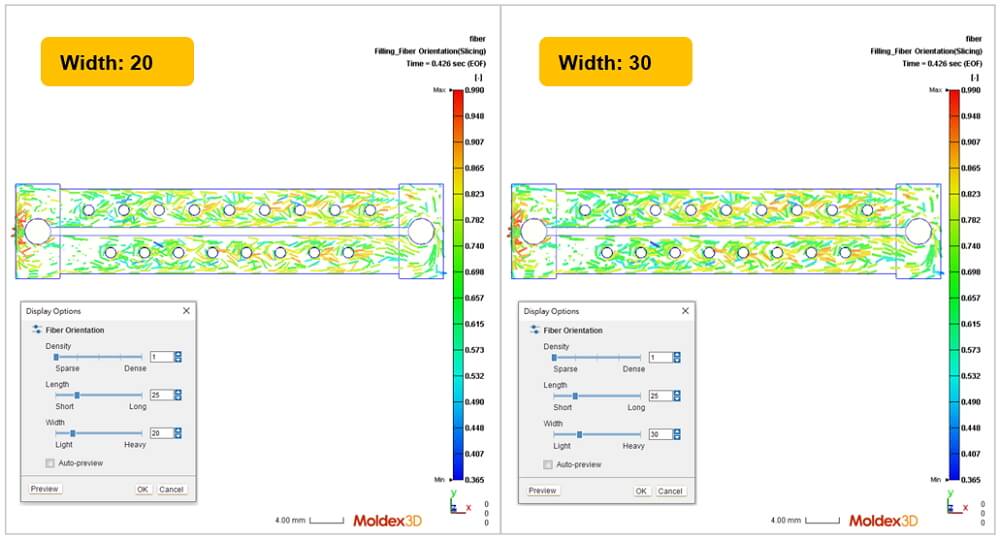
Right-click on the Fiber Orientation result and select the Display Options to open the control panel. There are three options in the control panel: Density, Length, and Width. Click Preview to view the effect of current settings and then click OK to apply the settings.
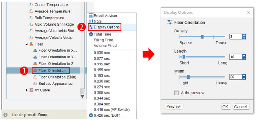
- Density: Adjust the quantity of the fibers displayed.
- Length: Adjust the length of the fibers displayed.
- Width: Adjust the line width of the fibers displayed.
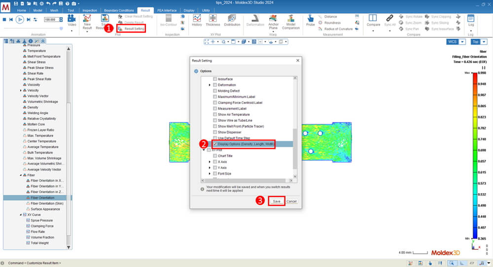
Note: The Display Options can be applied to Fiber Orientation, Fiber Orientation (Skin), Velocity Vector, and Average Velocity Vector. In Result Setting, users can mark Display Options (Density, Length, Width) to save the current settings as shown in the picture below:
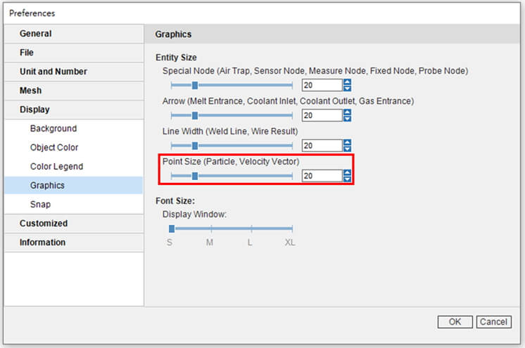
In addition to the display of Fiber Orientation mentioned above, there are more Display options in the Preferences setting. Previously, the Graphics settings can adjust the font size and entity size of specific objects (e.g. probes, arrows of the melt entrance). Point Size is now added to change the particle size in Particle Tracer results or the endpoint size in Velocity Vector. These improvements enhance clarity in result displays, better satisfying users’ needs.