Shell Mesh offers numerous advantages in simulation and is particularly suitable for simulating thin-walled parts. It significantly reduces computation time and resources, and can quickly validate the design in the early stage, enabling more efficient product development. To meet the demands of Shell Mesh modeling, Moldex3D Studio 2025 introduces several new functions. For example, T Stitch enables users to quickly connect non-matching mesh points, achieving precise and efficient mesh integration. Additionally, Property further enhances the flexibility and convenience of creating Shell Mesh, streamlining design modifications and pre-processing, thereby saving users substantial modeling time.
In Moldex3D Studio 2025, Melt Channel is a new feature specifically designed for Shell Mesh modeling. Melt Channel is a property curve used to simulate flow channels and enhance melt flow performance. When the melt flows into the Melt Channel region, it significantly improves flowability, resulting in more accurate simulation of the melt front behavior. This feature simplifies the flow channel design process while strengthening the applicability and efficiency of Shell Mesh in simulation analysis.
The following outlines the steps and tips for Shell Mesh modeling using Melt Channel.
Step-by-step Procedure
Limitation
- Melt channels are only supported in Shell Mesh.
- The endpoints of a Melt Channel curve must be on mesh points (It is recommended to use Extract Mesh Edges).
Pre-processing
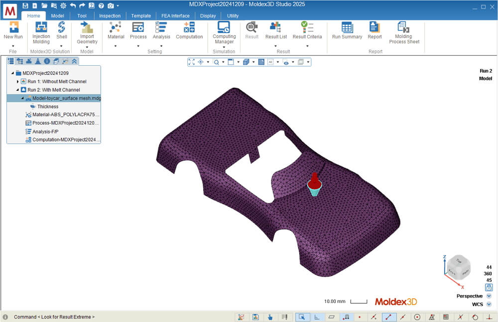
Step 1: Open a Shell Mesh project in Moldex3D Studio. Run 1 includes a part with uniform thickness (1 mm) and no Melt Channel used. Run 2 is a duplicate of Run 1 and doesn’t set Melt Channel yet.
Step 2: In Run 2, switch to the Tools tab and click on Extract Mesh Edge. Select two mesh edges where the Melt Channel will be created, then click  to generate two curves.
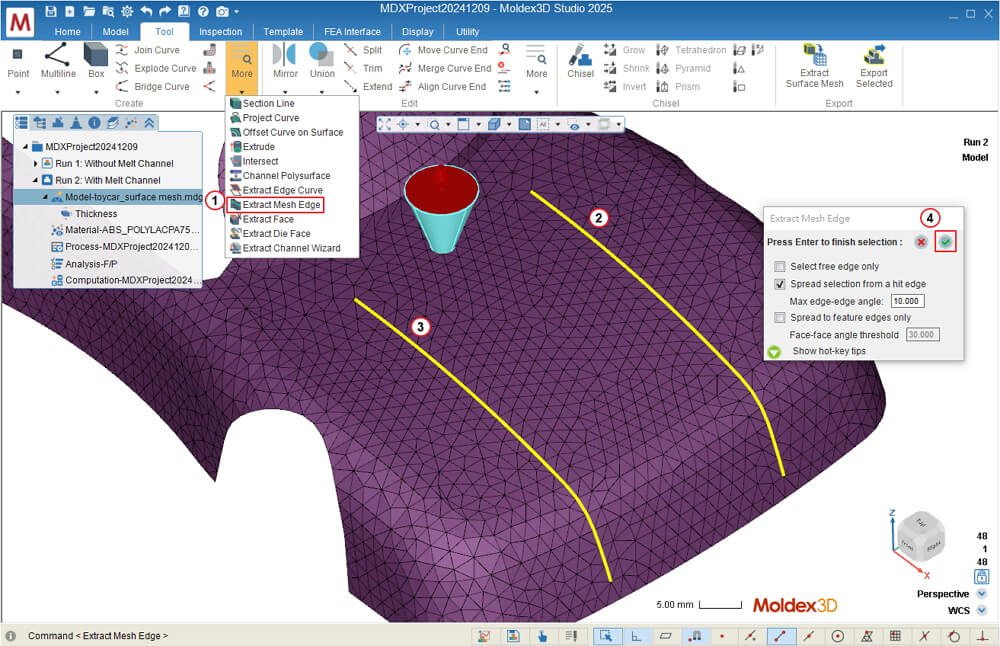
Note 1: In this case, the two extracted mesh edges correspond to the positions of feature lines. If the model does not have feature lines, users can apply Divide Face to create feature lines and then generate the mesh.
Note 2: If Extract Mesh Edge is not applied, users need to connect the mesh to the two endpoints of the curve manually.
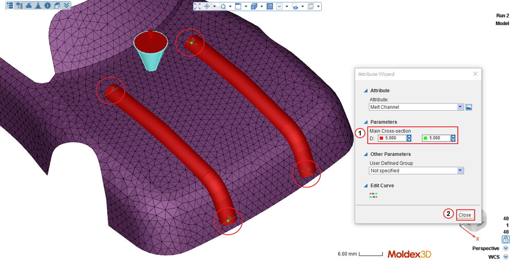
Step 3: Select the two curves in the model tree, right-click, and select Attribute to set them as Melt Channel.
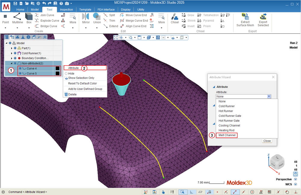
Step 4: Set the diameter at both ends of each melt channel as 5 mm. Once the settings are done, click Close.
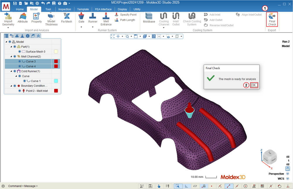
Step 5: Click Final Check and press OK to complete the pre-processing.
Analysis Setting
After completing Material Selection, Process Condition, and other analysis settings, select Filling & Packing – F/P in the Analysis Sequence and submit the run for analysis.
Result Display
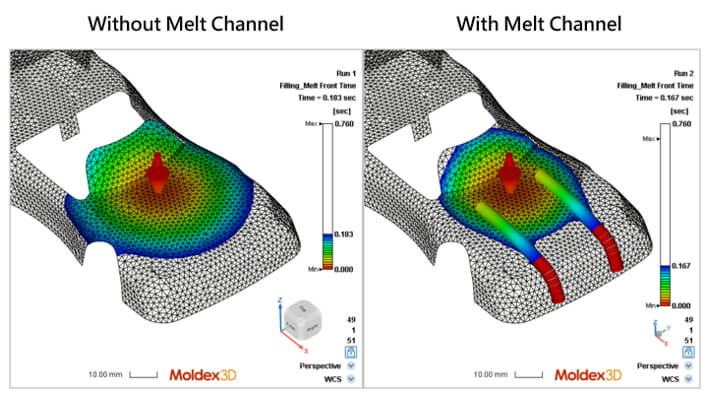
The image below illustrates the impact of Melt Channel on melt front in the model with a uniform thickness of 1 mm. It compares two scenarios: Without Melt Channel (Run 1) and with Melt Channels on both sides (Run 2), both with a diameter of 5 mm. The results show that the Melt Channels significantly improve flowability, enabling the melt front to pass through the Melt Channel regions more quickly.