In injection molding, the cooling system is of paramount importance. Molded parts must be cooled and solidified to a specific temperature to ensure sufficient rigidity upon ejection, preventing deformation and ensuring dimensional stability. In addition, cooling typically accounts for 70%-80% of the entire injection molding cycle, a well-designed cooling system can significantly shorten cycle time and improve overall productivity.
However, for molds used in large products, the cooling channels are often numerous and complex. This complexity frequently requires considerable time to organize and map out the inlet and outlet pathways of the various cooling circuits before conducting any analysis. Moldex3D Studio’s Cooling Channel Loop Wizard provides convenient tools for organizing and editing cooling lines, speeding up pre-processing. By representing cooling channels as lines instead of 3D solid models, it reduces the risk of mesh generation failures. This feature significantly enhances simulation efficiency and speed.
Cooling Channel Loop Wizard can automatically select the longest suitable cooling channel curve and mark the inlet and outlet positions. Given the prerequisite of having 3D solid cooling channels and information about inlet and outlet locations, the feature enables the rapid creation of cooling channel loop curves. This article demonstrates how to use Central Line and Connect Channel Curve, and then complete the cooling channel loop and inlet/outlet configuration using Cooling Channel Loop Wizard*.
*Note: The functions introduced in this article are for demonstration purposes only. The Cooling Channel Loop Wizard supports a wider variety of functions for creating cooling channel curves.
Step-by-step Procedure
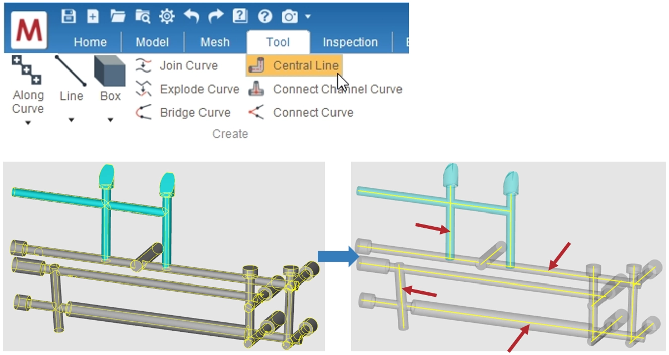
Step 1: Extract the Central Lines of Cooling Channels
After importing the geometry, use Central Line from the Tool page to extract the central lines from the 3D solid cooling channel geometry in the model. Then, frame-select the group of solid cooling channel surfaces from which the center lines are to be extracted. Multiple groups can be framed simultaneously. Once the selection is complete, click OK to extract the central lines. (shown as yellow curves in the lower-right figure)
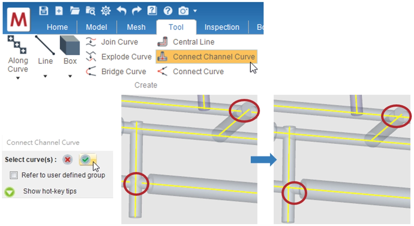
Step 2: Connect the Incomplete Cooling Channel Lines
Select Connect Channel Curve from the Tool page. Next, frame-select the previously generated central lines. Click the green checkmark to complete the process. Once completed, the previously disconnected lines will automatically be connected.
Step 3: Configure the Cooling Path and Set Inlet/Outlet Points
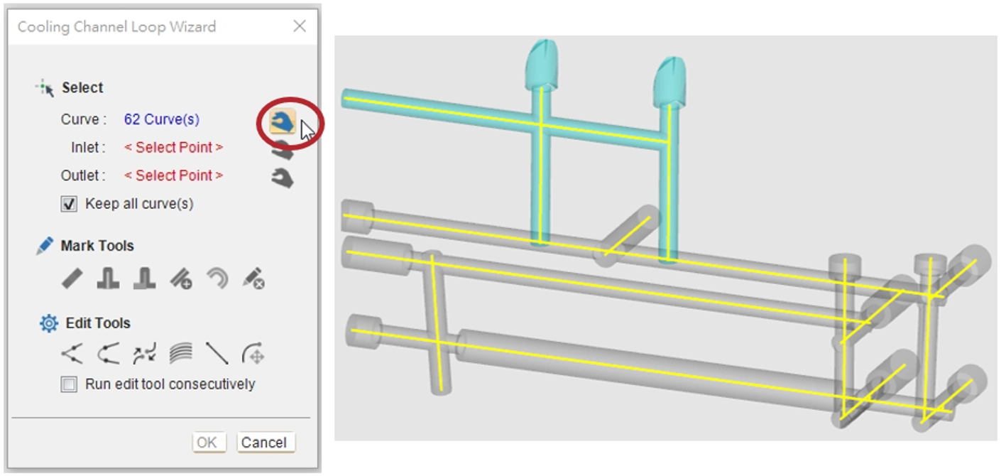
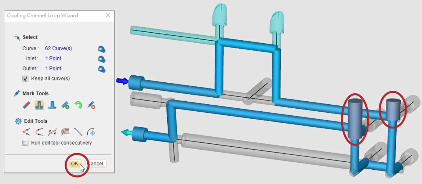
Click Cooling Channel Loop Wizard under Loop Wizard from the Model page. Frame-select the connected cooling channel lines, then click the capture button to complete the selection.
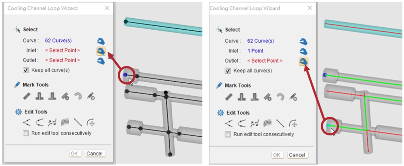
Click the inlet point capture button, and then select the inlet point. Once completed, the endpoint will turn blue. Follow the same steps for the outlet point, which will be marked in green. After both points are set, the feature will calculate and display the longest suitable cooling channel path, highlighted as a green line.
Mark Tools and Edit Tools in Cooling Channel Loop Wizard
Mark Tools
Cooling Channel Loop Wizard offers six Mark Tools to mark blocking segments or define the properties of specific segments of the cooling channel based on the mold’s cooling requirements. These tools are Mark Block, Mark Baffle, Mark Bubbler, Mark Extra Channel, Mark Hose, and Remove Mark.
Edit Tools
Additionally, six Edit Tools are available in Cooling Channel Loop Wizard to modify the existing channel segments. These tools are Connect Curve, Bridge Curve, Merge Curve End, Between Curve, Line, and Move Curve End.
Mark Tools Demonstration: Mark Block, Mark Baffle
Step 1
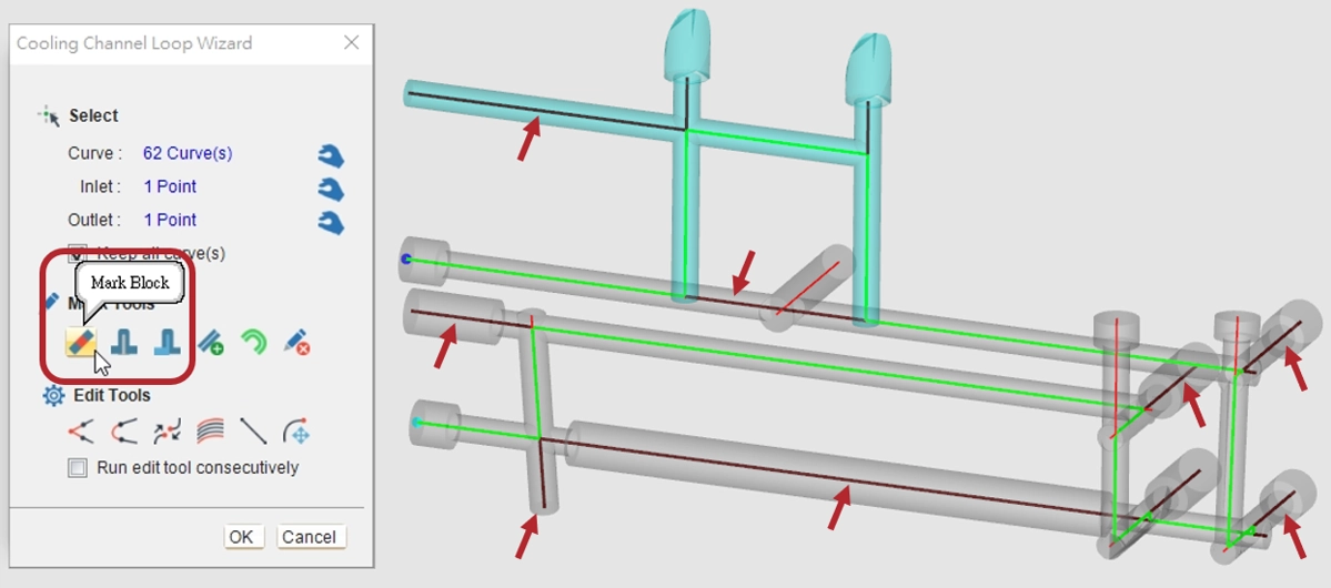
Select Mark Block and choose the line segments where the stop plugs should be placed to block the cooling channel flow. The selected line segments will be displayed in black.
Step 2
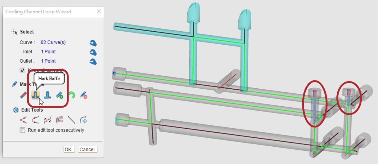
Next, click on Mark Baffle and the selected line segments will change color and become thicker.
Step 3
Once completed, the defined cooling channel system, including the inlet and outlet positions, will be displayed. All marked segments will be automatically grouped into the cooling channel configuration.
Edit Tools Demonstration: Connect Curve, Bridge Curve
Step 1
From the connected cooling channel center lines, select the channel group to be configured. Enter the Cooling Channel Loop Wizard interface to frame-select the cooling channel group and define inlet and outlet points.
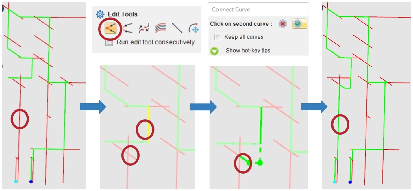
Step 2-1: Connect Curve
If the generated path (green line) does not connect to the outlet (cyan endpoint) due to a missing curve, click on Connect Curve and select the endpoints of the disconnected lines — in this case, the endpoint of the yellow line segment and that of the unconnected red line segment. Once completed, a new continuous cooling channel (shown as a green curve) is generated, connecting the inlet and outlet.
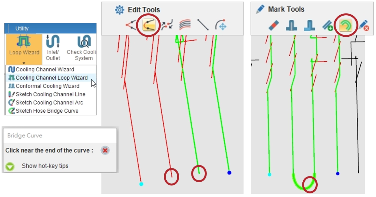
Step 2-2: Bridge Curve
If the generated path (green line) does not connect to the outlet (cyan endpoint) due to a missing external curve, click on Bridge Curve to connect the red and green channel groups. Select the two endpoints to be bridged, and a bent curve is generated to link the disconnected channel groups into a continuous cooling path. Moreover, the Mark Hose tool can designate the newly created bent curve as a hose. Once marked, the segment is displayed as a thicker green hose curve.
Finally, use Cooling Channel Loop Wizard to organize other cooling channel groups. The feature will generate individual paths and automatically assign them to their respective groups. This process results in a fully connected and well-organized cooling channel system, simplifying management and enabling efficient analysis.