
Daniel Hsiao, Senior Engineer at Technical Support Division of CoreTech System (Moldex3D)
Shell Model Introduction
The shell model is a commonly used method in finite element analysis, where the simplification of the model involves ignoring the thickness dimension. The 3D geometry is transformed into a 2.5D model, which reduces computational resources and facilitates design modifications. This approach eliminates the need to generate a dense mesh in the thickness direction, enabling simulation analysis to be completed without the need for extremely high computational resources. This simplification is particularly suitable for simulating thin shell structures or components with large differences in thickness and length.
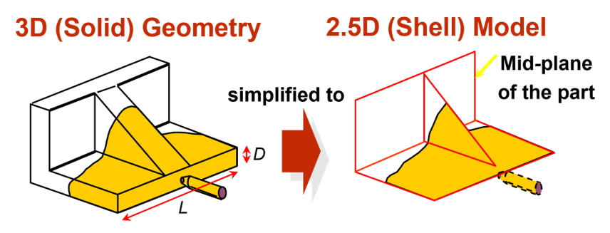
Fig 1 Simplified diagram of the model
Although the Shell modeling enable fast simulation without the need for high-performance computers, the conversion from 3D model to 2.5D mesh requires the efforts of time-consuming preprocessing process. Moldex3D Mesh (Rhino) and Moldex3D Studio provide powerful tools to develop Shell model from 3D geometry. In this example, we’ll illustrate the steps of mesh preprocessing for the Toycar model in Studio.
Section 1: Mesh pre-processing
Step 1: Import Geometry
First, open the project and select the Shell type. Then, import the geometry and configure it as shown in the image above.
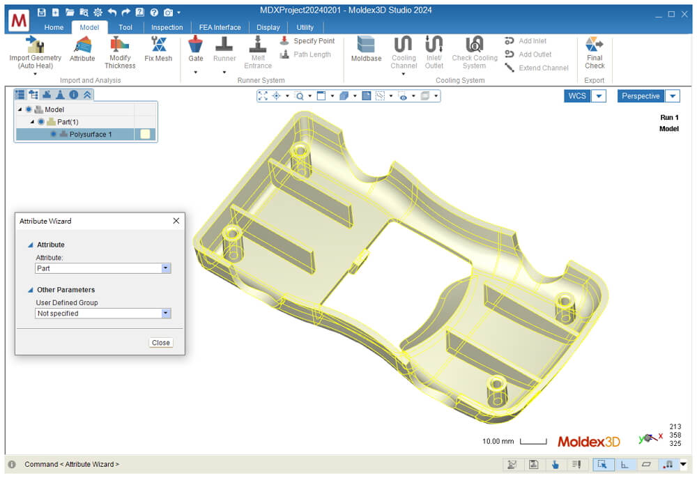 Fig 2 Import Geometry
After selecting “Model” on the main page, then Click the Create Face Mesh under Fix Mesh continue selecting the intermediate surfaces by pressing the Shift key, as indicated by the yellow area in the figure below. Make sure NOT to check “Mixed Elements” and “Grid-based Element“, click OK, and the mesh will be generated as shown in the Fig.3 below.
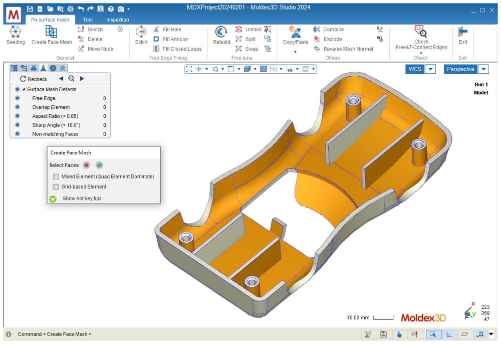 Fig 3 Choose middle surface
Step 2: Check Free&T-Connect Edges
Set the Attribute for all mesh as part next hide the portions of the mesh that consist of ribs and cylinders. Proceed with Check Free Edges & T-Connectivity Edges, and a pop-up window will appear. Check Create Curves to display the corresponding free edges, as shown in the figure 4 below.
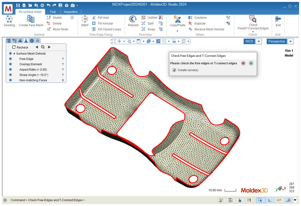 Fig 4 Show Free edges
Step 3: Fix Surface Mesh
In the Fix Surface Mesh tab (see figure 5), establish the order for creating filling meshes:
1. Click on Fill Closed Loops; 2. Click on the command; 3. Select the free edges; 4. Click on the green check mark; 5. Repeat steps 3 and 4, then select another 7 free edges. After confirmation, all the mesh fillings will be generated.
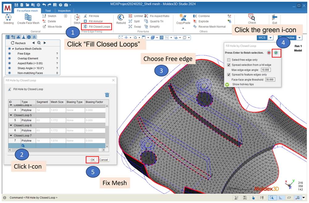 Fig 5 Fill Closed Loops
Step 4: Setting Thickness
Exit the Fix surface Mesh function, unhide the hidden objects, then click Modify Thickness. First, select all the mesh and set the thickness to 2.5mm. Then, utilize the selection feature to set the thickness of the four ribs to 2mm.
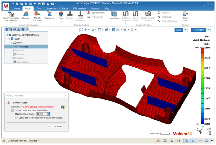 Fig 6 Model Thickness
Section 2: Finish Model Preparation and Run Analysis
Step 5: Setting Runner Mold base Cool system final check
In the Model Tab, Click Gate and Runner to assign the gating location and generate the runner system automatically. Click Moldbase and Cooling Channel to generate cooling system model with default parameters. Click Final Check to confirms the completion of mesh pre-processing.
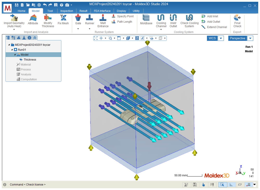 Fig 7 Final Check model
Step 6: Setting Material\Process\Start Analysis
After completing the Final Check, you can set the Material, Process Condition and Analysis Sequence (C F/P C W). Then, Click Run to start the analysis with Shell solver on Computing Manager. The results will be loaded back in Studio once analysis completed
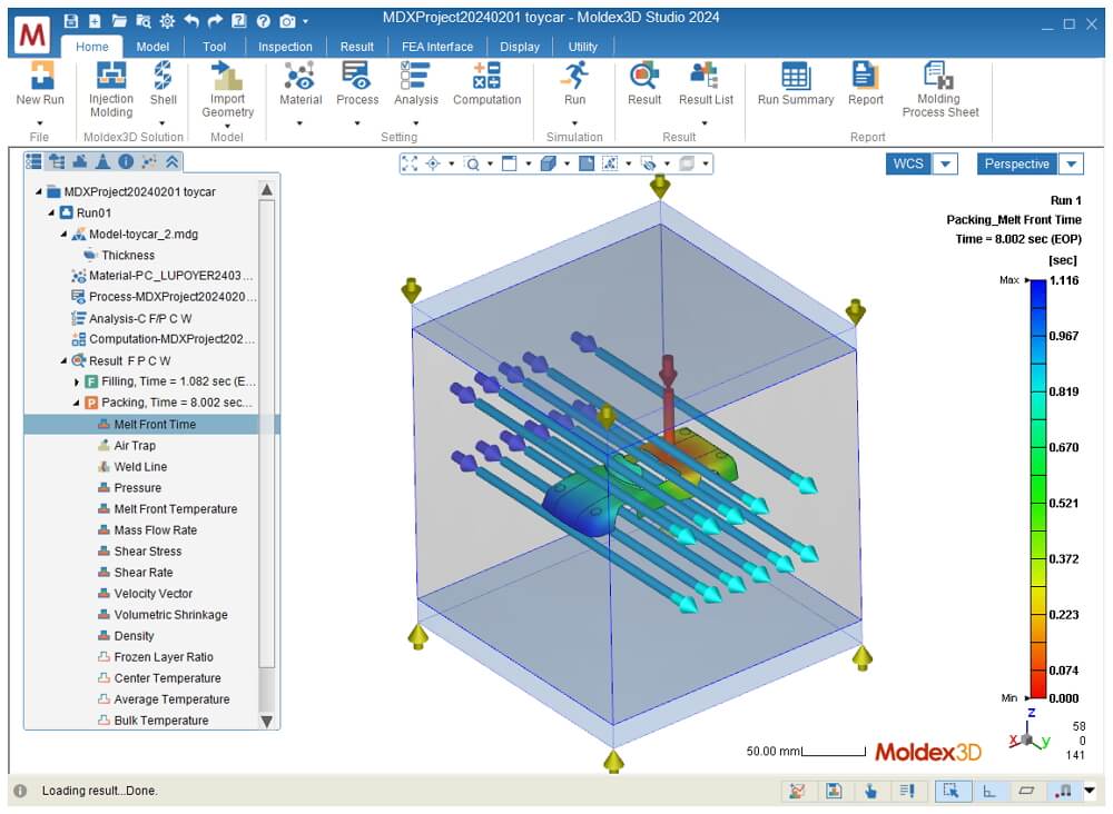 Fig 8 Melt front Time Result