In the filling stage of epoxy molding compound in IC encapsulation process, high melt viscosity and fast flow can worsen wire sweep problems. A serious defect followed by wire sweep is wire short problems, which happen when a wire deforms and contacts to another wire in the molding process.
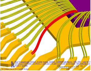
Moldex3D provides wire sweep prediction and wire sweep index for user to determine if the setting of processing conditions, the selection of materials, and leadframe layout is appropriate. In figure 2, the position of wire cross over is shown in a closer look. In the wire crossover display, the shape of wires are shown as deformed mesh on true scale, and wires contact each other will be marked in red, while other wires remain theirs original color.
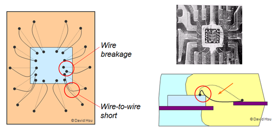 Fig. 1 Defects like wire-to-wire short of wire breakage caused by wire sweep
Venting analysis is available in Moldex3D palstic injection molding software. The purpose of setting up venting is to avoid negative effects brought by the air trapped in injection molding process. Poor venting designs may cause serious molding problems such as burn marks, flash, short shots, air traps, poor surface finish, excessive molding shrinkage and so on. Moldex3D considers venting effects when running injection molding and IC encapsulation simulations and provides accurate predictions on the pressure and temperature of air traps, which are the factors of incomplete fill and burn marks, as shown in Figure 1.
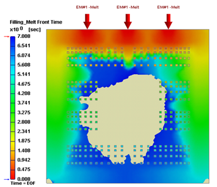 |
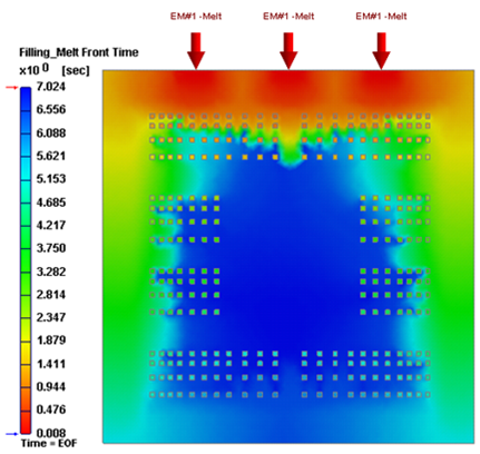 |
Fig. 1 No venting with initial pressure=0.1MPa |
Venting with initial pressure=0.0001MPa |
Tip: Users can specify venting designs in one mesh model by Moldex3D Designer and venting control in process setting more quickly and efficiently.
-
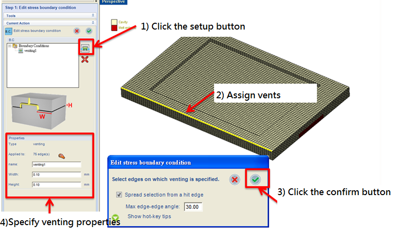
Specify venting boundary in Moldex3D Designer
-
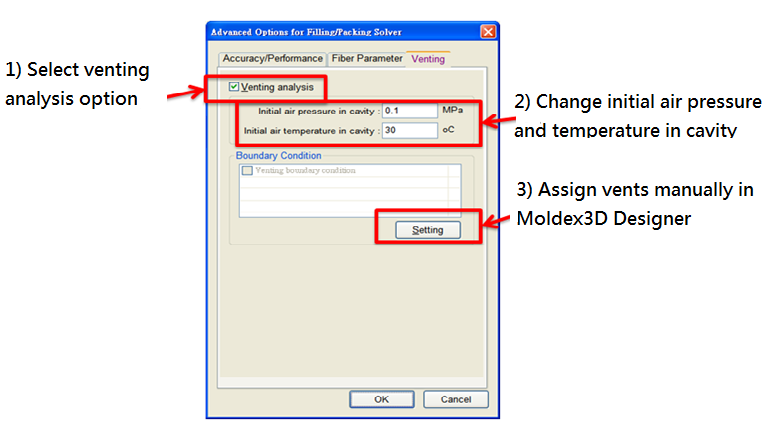
Venting setting in advanced option of process setting
