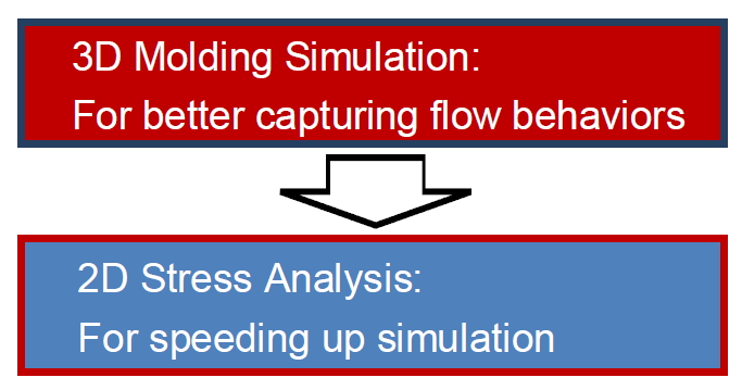
Combining Moldex3D and LS-DYNA enables more accurate structural analysis, considering the molding-induced effects. A 2D shell model requires less FEA solver computation time and can therefore enable faster results. However, for more accurate results in molding simulation, the 3D model of Moldex3D is used to capture detailed variations of flow behaviors in the part in injection molding analysis. To achieve a balance between accuracy and efficiency, Moldex3D supports efficient data mapping from 3D injection molding analysis to 2D FEA meshes for LS-DYNA structural analysis. The following step-by-step instruction will guide users to go through the workflow of mapping process-induced properties from Moldex3D to LS-DYNA
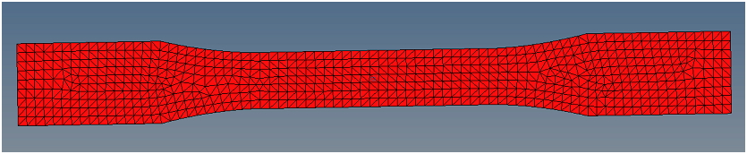
Step 1: Prepare a shell mesh for LS-DYNA FEA solver and a 3D solid mesh for Moldex3D solver.
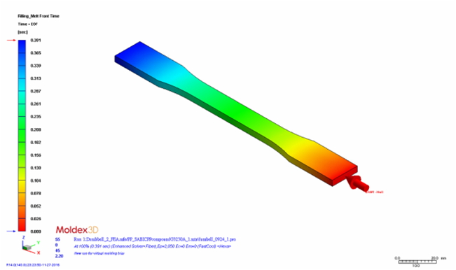
Step 2: In Moldex3D, import the 3D solid mesh and complete injection molding analysis. Then, launch Moldex3D FEA Interface to map the analysis result to the shell mesh.
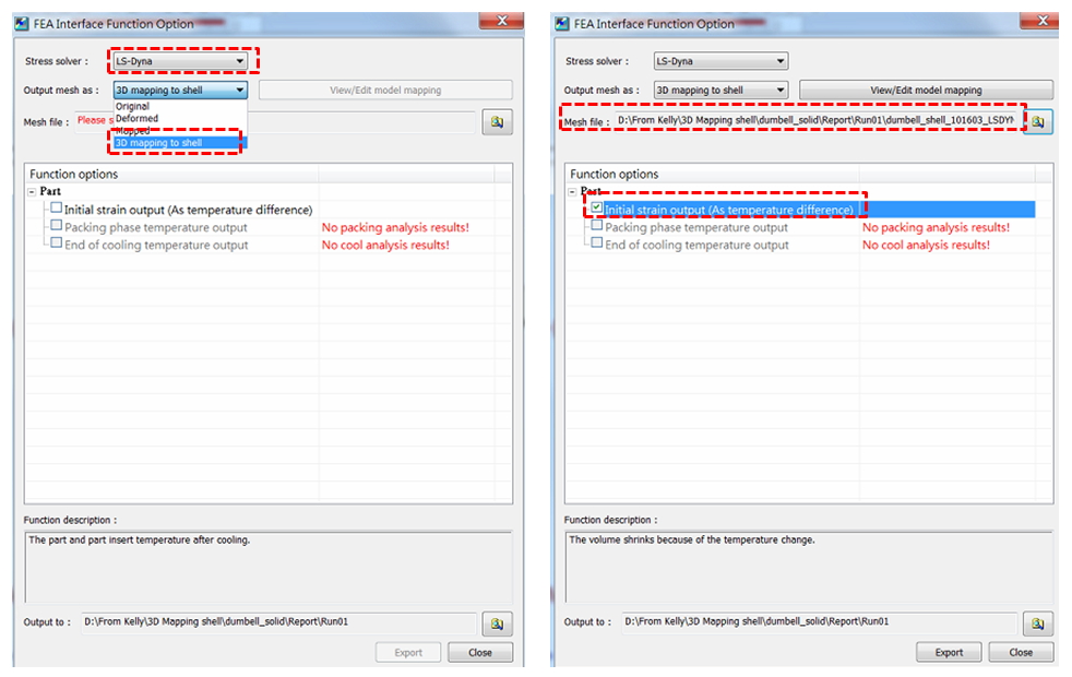
Step 3: In Moldex3D FEA Interface, select LS-DYNA as the stress solver, and select “3D mapping to shell” as the output mesh. Specify the shell mesh file created at step 1 and output the items listed in Function options (Initial strain output shown here).
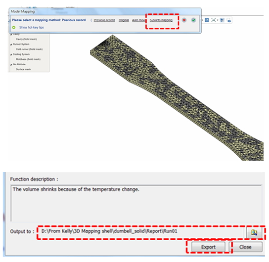
Step 4: Click View/Edit model mapping and click 3-point mapping to adjust the positions of the 3D mesh and shell mesh by specifying 3 reference points on both mesh models.
Then, specify a path for output destination, and click Export to output the data to the target mesh model.
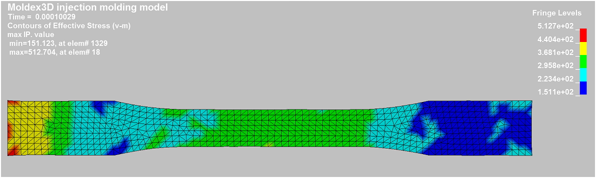
Step 5: Import the mapped shell mesh and run a stress analysis in LS-DYNA. When the calculation is completed, the analysis result considering molding induced effect, such as stress plotting, can be observed below.