사출 금형 제품의 성능은 사출공정 동안 물성치의 비등방성을 고려한 FEA소프트웨어를 사용하여 예측 가능하다. 2013년 10월호인 뉴스레터에서 Moldex3D Digimat FEA Interface를 소개하였다.
본문에서는 Dagimat과 FEA 소프트웨어에서 섬유 방향이나 Cell 분포 정보를 외부 파일로 생성하는 방법과 절차를 설명한다.
Digimat과 FEA(i.e. marc) Interface에 섬유 방향과 메쉬 정보를 생성하기 위하여 *.o2d 파일과 *.dat 파일이 필요하다. *.o2d 파일은Moldex3D FEA interface에 있는 Digimat 내보내기 기능으로 생성한다. *.dat 파일은 Stress solver에 Marc를 선택하여 변환한다.
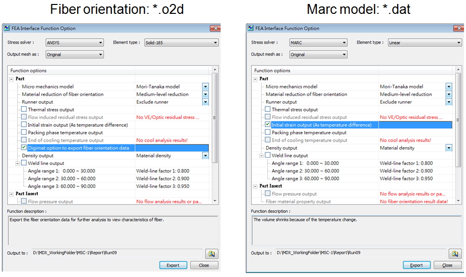
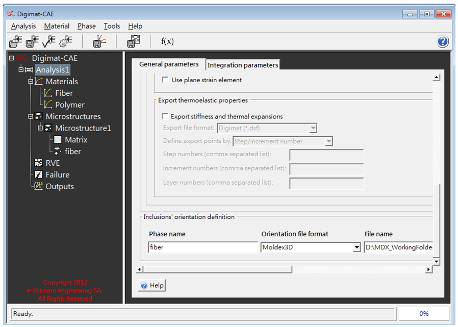
*.o2d 파일은 배양성을 정의하기 위하여 Digimat에서 데이터를 불러들인다.
Fiber/Matrix 미세구조는 데이터를 불러들이기 전에 할당되고 분석되어야 한다. Marc 해석을 위하여 *.marc와 *.mat 파일이 필요하다.
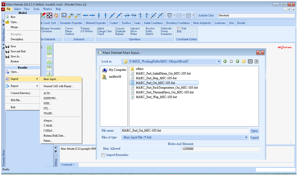
*.mat 파일을 이용하여 *.dat 파일을 생성하여 구조해석을 위한 Marc로 불러들인다.
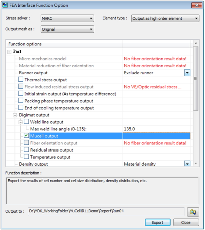
Mucell Gas Bubble 미세구조를 생성할 때로 위와 동일한 절차를 수행한다.
*.m2d 파일은 Cell 밀도와 각 요소에 대한 평균 Cell 크기를 포함한다.
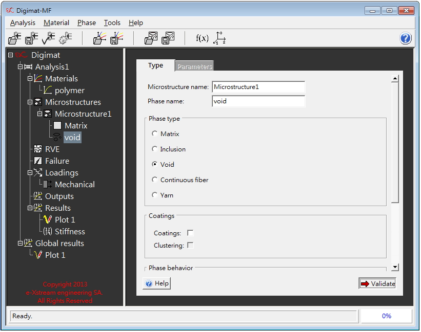
Void는 Digimat 미세구조 복합체를 할당할 때 폴리머 matrix 내부에 second phase로 선택해야 한다.