Matching surface meshes between parts and part inserts will ensure more accurate simulation results; however, it often takes a tremendous amount of time and manual effort. The Gate Rebuild tool in Moldex3D can help users refine the mesh in the gate area to more accurately describe the complex flow behavior around the gate. However, after applying the Gate Rebuild, there’s a chance that the matched meshes between the part and the part insert in the gate area may become unmatched. To solve this issue, Moldex3D Studio now supports keeping these contact faces between part and part insert matched after rebuilding the gate.
Since different components require different mesh resolution to obtain certain simulation accuracy, it is necessary to adjust mesh parameters for each component. Moldex3D now provides a more flexible and easy way to help users specify BLM parameters for each component, including part and mold insert. Please follow the steps below to learn how to keep mesh matched after rebuilding the gate and learn how to specify BLM parameters for each component.
1. Keep contact faces matched after rebuilding the gate
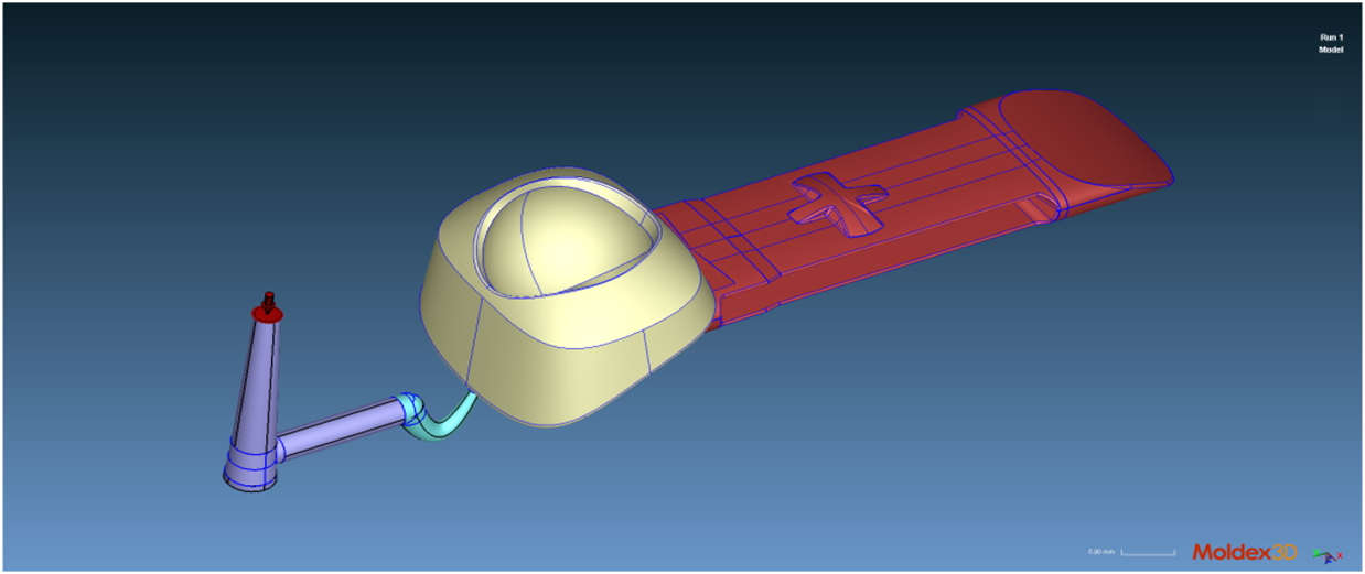
Step 1 Prepare a model with CAD components of part, part insert, and gate.
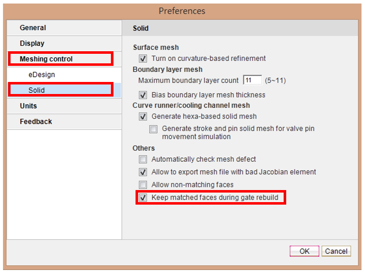
Step 2 Click preferences (  in Studio Quick Link) to enable the Keep matched faces during gate rebuild in the Solid tab under the Meshing Control and click OK to apply.
Note: This will ensure the matched faces during Gate Rebuild, so the option Allow non-matching faces (same page) should be disabled.
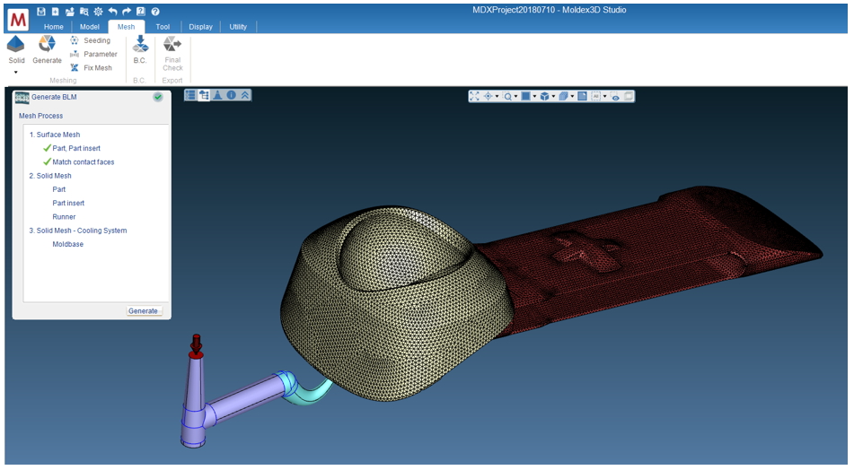
Step 3 Launch Generate BLM Wizard in Mesh Tab and click Generate to create a surface and solid mesh for the part and part insert.
Note: You might need to match the faces between part and insert meshes if the automatic matching function is not suitable for more complex models.
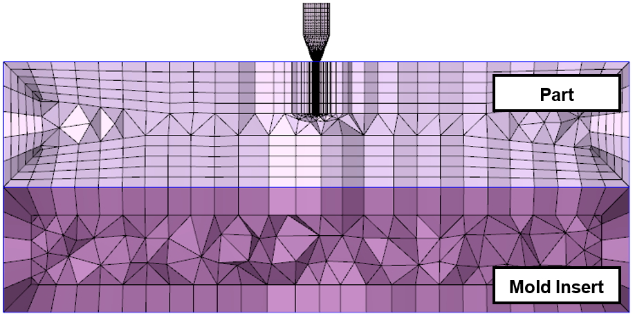
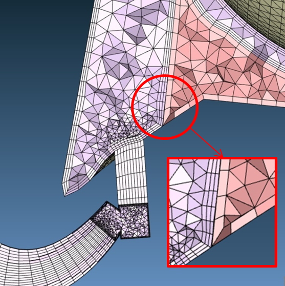
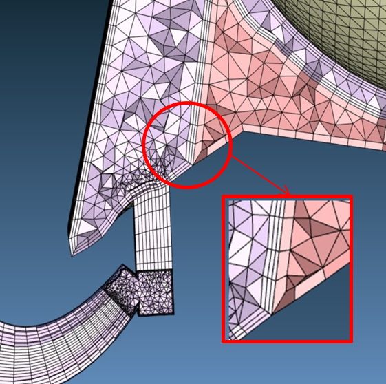
Step 4: After generating the solid mesh on the gate and the runner, the original solid mesh between the part and the part insert remain the same. Users can use the Chisel tool to check whether the mesh is still matched or unmatched.
| Option disabled | Option enabled: Keep matched faces after the gate is rebuilt |
 |
 |
2. Set BLM parameters on Mold Insert
Step 1 Prepare a model with mold insert and set solid mesh parameters.
Step 2 In Mesh tab, Click Parameters  and choose Mold Insert in Attribute to set BLM parameters for Mold Insert (1 Layer BLM and 1 Manual offset ratio).
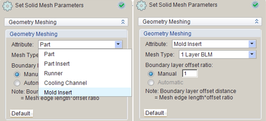
Step 3 Launch Generate BLM Wizard to generate the surface mesh and solid mesh on the model. The part has 5 layers BLM and an offset ratio of 2, while Mold Insert mesh has 1 layer BLM and an offset ratio of 1 (Use Chisel tool to better check meshing result).