
Valve gate is one of the key components in a hot runner system, such as multi-gate system. The valve gate can be either shut off to prevent the melt from entering the cavity or opened to release the melt into the cavity under certain controls. This feature is important since multi-gate system is susceptible to particular issues like weld lines. Furthermore, a proper valve gate control can help users minimize the variation in flow density, which is a common cause of stress marks or pressure transition marks that can appear as undesirable surface defects such as uneven gloss or reflection marks.
Moldex3D allows users to freely choose specific controls that meet their needs. For example, time, flow front, or ram position control can be chosen to open or close the valve gate. Moreover, this valve gate control function supports not only filling stage but also packing simulation. It provides users with a comprehensive control of the system.
Prepare the mesh model for valve gate control analysis in Moldex3D Designer
Step 1 In Designer, first prepare a model with a hot runner system, and specify valve gate control ID using either of the following two ways:
Note: In Moldex3D-Mesh, Valve Gate ID can only be specified in hot runner solid mesh attribute setting; thus, users must finish hot runner solid mesh generation first.
| At Step 2 in the picture below (Before Solid Mesh Generation) |
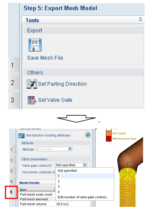
At Step 5 in the picture below (After Solid Mesh Generation) |
| Set Valve Gate Control ID when assigning hot runner attribute
|
1. Click Set Valve Gate 2. Set Valve Gate Control ID
|
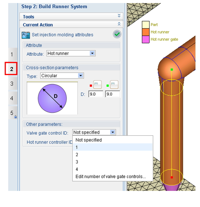
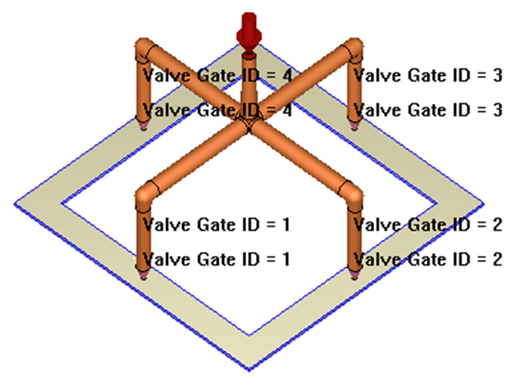
Note: For both categories, users are recommended to set the Valve Gate Control ID for the whole hot runner drop, not only the hot runner pin gate. The final mesh model looks like below:
Set the analysis for valve gate control in Moldex3D Project
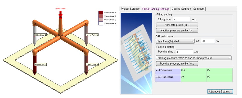
Step 2 In Project, create a new project and run, import the mesh model, and finish general analysis settings. For Valve gate control setting, click Advanced Setting in Filling/Packing tab of Process Wizard, and go to Valve Gatetab.
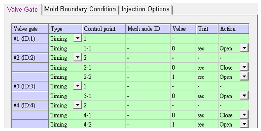
Step 3 Set the Control Point number for how many actions that the valve gate will perform respectively, and specify the Action to either open or close the valve gate to perform when reaching the control point. To perform different control settings, change Type for each valve gate ID with 3 different control options supported: Timing, Flow Front, and Ram Position.
Note: Beware of the Valve Gate ID to ensure valve gate actions are as planned; different options of Type can only be selected for different valve gate IDs.
Timing Control:
- Set the Value with Unit in seconds (sec) to represent the time when the action is performed.
Note: If the filling time and packing time are corresponding to the time value of the valve gate control, this action can be performed during both filling and packing stage; the control during packing stage can only be set when using Timing type.
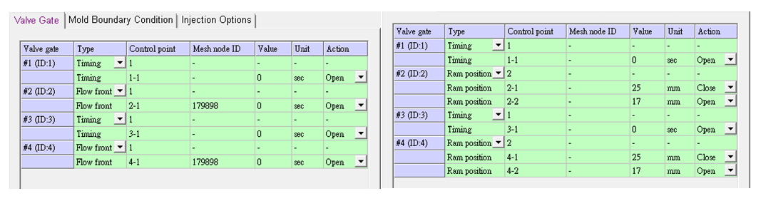
Flow Front Control:
- Set the Mesh Node ID to represent when the action is performed.
Note: It means that the valve gate will perform the action after the melt front reaches certain mesh node, and its ID can be obtained using the function Select.
- Set the Value with Unit in sec to represent the delay time when the action is performed.
Note: The time value here (delay time) is different from the time value for timing control (action time).
Ram Position Control:
- This function is available only when the process is set using Machine Mode (1 & 2), and is not supported in CAE Mode.
Set the Value with Unit in mm to represent the ram position where the action is performed.
Note: users must be familiar with the relation between the ram position and the filling percentage or stroke time.
The analysis and result interpretation of the valve gate control in Moldex3D Project
Step 4 Run analysis with sequences of Filling and Packing, and check molding performance, such as weld line location, filling balance or pressure variation, according to the analysis results.
| 50% Filling (Case of Timing Control) | 90% Filling (Case of Timing Control) |
|
Valve gates 2 and 4 open at filling time of 1 s (or 50% filling since the filling time is set 2 s). |
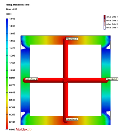
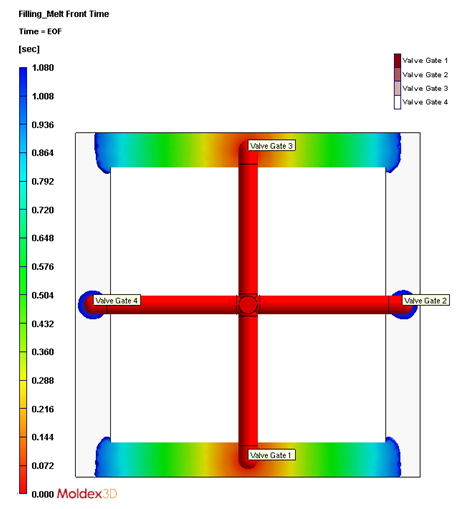
From 90% filling, users can see where the melt fronts will meet and converge. |
| 27% Filling (Case of Melt Front Control) | 17-mm Ram Position (Case of Ram Position Control) |
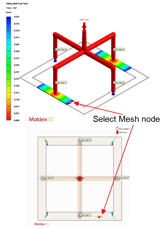
Valve gates 2 and 4 open after the melt front from valve gate 1 reaches the set mesh node. |
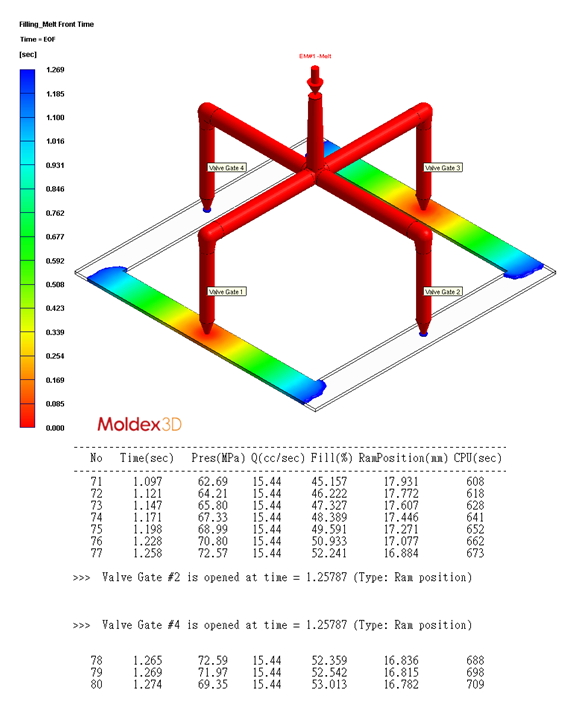
Valve gates 2 and 4 open after the ram position reaches 17 mm. |
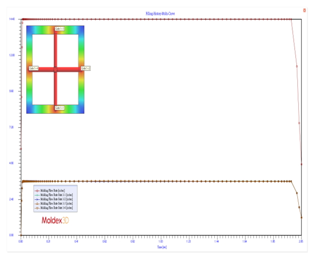
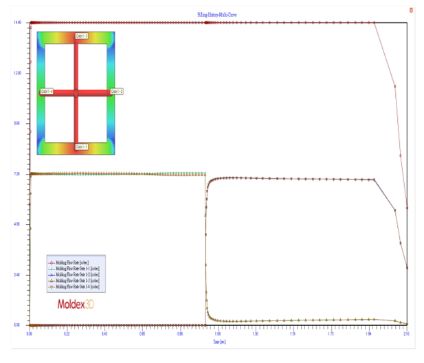
In addition, below are the flow rate graphs for the abovementioned conditions:
| Without Valve Gate Control | With Valve Gate Control |
|
|
|
Extended applications using valve gate control analysis
- Improve weld line locations or eliminate weld lines
The key procedure section to improve weld line locations has been interpreted in the previous three examples (the case when weld lines are inevitable).
- Improve flow density
Besides weld line issues, proper valve gate control can also improve the flow density, making the pattern more uniform across the part.