Combining draping (thermo-stamping) and injection molding to process Continuous Fiber Reinforced Thermoplastics (CFRT) is a preferred solution for manufacturing high volume products. In order to create a qualified composite part, the woven fabrics will be completely impregnated with resin and be formed by draping (from sheet shape) into a semi-product. Then the cavity will be further filled through injection molding process to form the finished part. During the draping process, the alignment of the continuous fiber will vary along the product geometry, and the fiber orientation will affect the product mechanical properties. To better consider the draping induced factors in injection molding simulation, Modex3D Multi-component Molding (MCM) module supports the orthotropic material settings of part insert by reading the draping analysis data from LS-DYNA.
The following step-by-step instruction will guide users to run the sequential draping analysis with LS-DYNA for the preform, followed by injection molding analysis in Moldex3D.
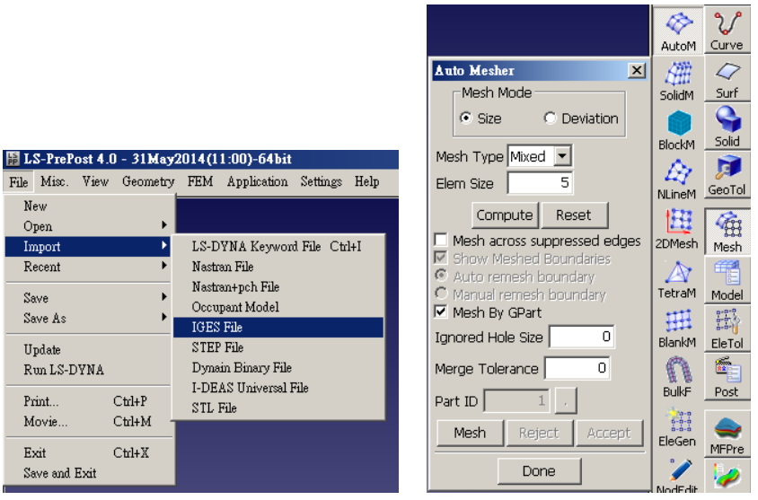
Step 1: In LS-PrePostpreprocessing, launch LS-PrePost 4.0 (LS-PP), import shell mesh model (IGS file), and apply Auto Mesher to generate mesh (LS-PP 4.0 or newer versions are suggested).
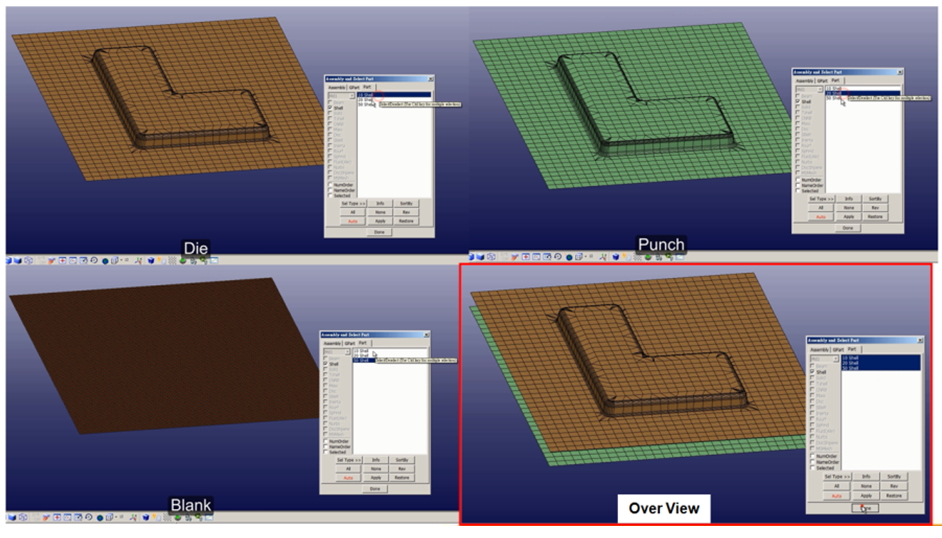
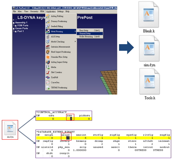
Step 2: In LS-PrePost Melt Forming analysis setting, set up a forming analysis sequence with property cards (234 and 235, fiber) for draping analysis.
Note: Make sure to set up the parameters: inn=2 and neips=20.
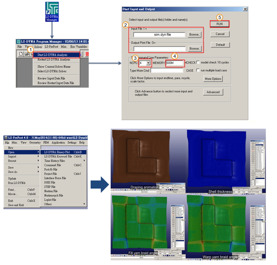
Step 3: In Draping analysis of LS-Dyna Solver, go to LS-Dyna Manager and launch dyn to run analysis. Go back to LS-Prepost after the analysis, and then read d3plot file to check the draping analysis results.
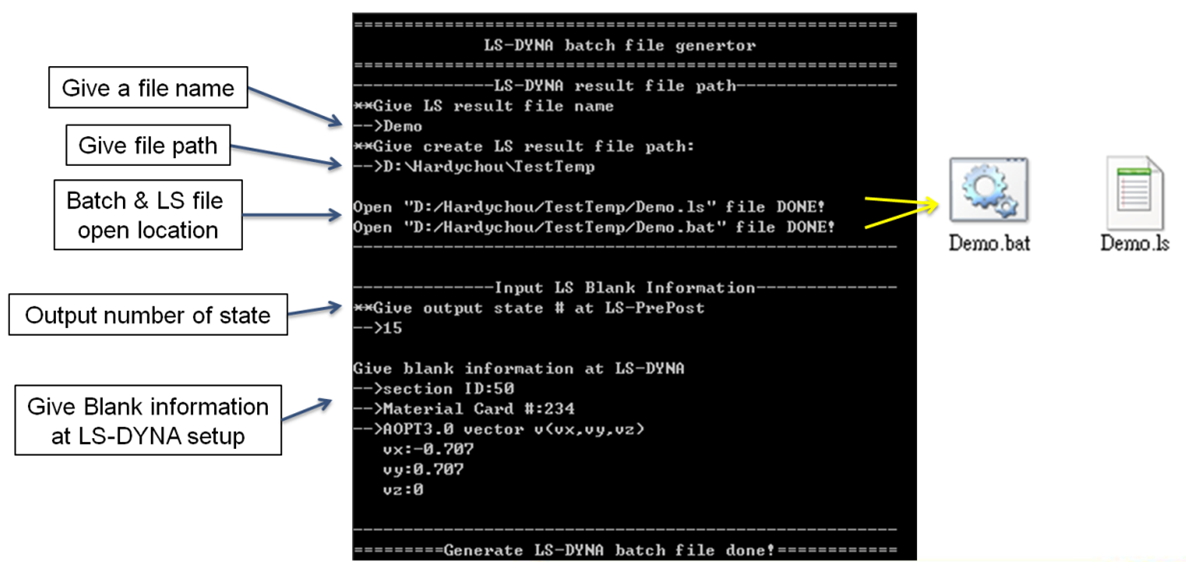
Step 4: LS file contains the fiber mat orientation and thickness data after draping. To export the LS file, launch EXE file (in Tools folder under Moldex3D installation pass), and then enter LS file name, path, and blank information. The BAT and LS files will be generated in the target path.
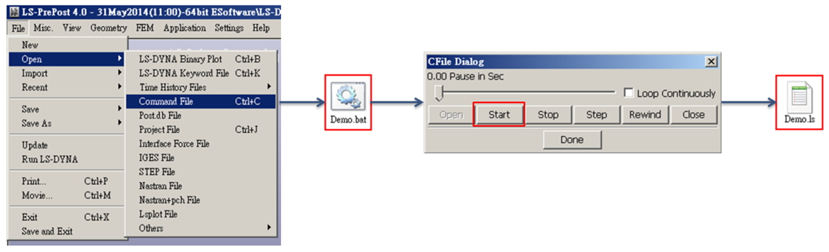
Step 5: Load d3plot file with LS-Dyna draping analysis result in LS-PrePost, and launch Command file function with BAT file generated previously to develop fiber mat orientation data in LS file generated previously. Note: Analysis in LS-Dyna only provides braid angle, and Moldex3D MCM project applies projection with LS file and braid angle to obtain fiber mat orientation.
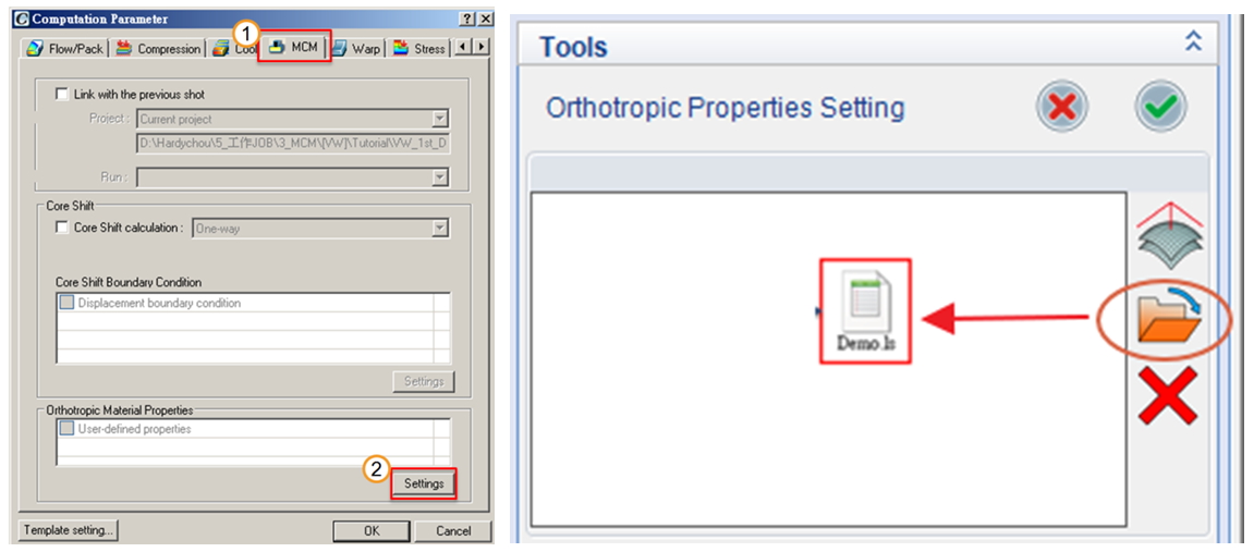
Step 6: In Moldex3D, create a new Injection Molding project with a 3D-Solid mesh model containing the part and part insert. To assign the orthotropic material with fiber information of the part insert, go to MCM tab in Computation Parameter of the MCM project. Under the tab, click Settings under Orthotropic Material Properties to launch the workspace and assign or modify the orthotropic material property. The option User-defined properties will be checked if any orthotropic material has been assigned.
Note: The 3D-Solid mesh model of the part insert can be prepared by extruding from LS-DYNA shell model or through any preprocessor supporting MFE.
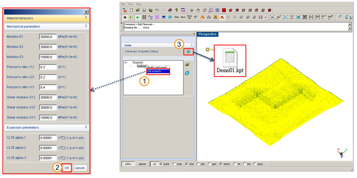
Step 7: In the workspace in the picture below, users can create, assign, import, and delete the orthotropic material data of the part insert. By expanding the dialog, users can modify the mechanical and expansion parameters in each axis direction.
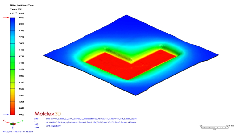
Step 8: Run this analysis in Moldex3D and the simulation results will be available when done.