Capillary Underfill (CUF) in IC packaging process involves dispensing epoxy resin on the side of the flip chip and filling the bottom of the flip chip by surface tension. Moldex3D IC Packaging module supports Capillary Underfill simulation. With that, users can simulate the capillary flow behaviors.
During the underfilling process, the flow front of epoxy is in contact with many different components, such as PCBs, solder balls, silicon dies, and more. The properties of surface tensions at contact faces vary with different components. In order to shorten the gap between simulation and the reality, Moldex3D takes the surface tension property into account by providing the contact angle parameter setting of epoxy with different components.
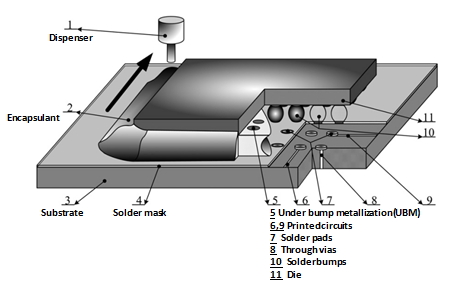
Flip-chip capillary underfilling process
Workflow – Specify the contact angle parameters of the epoxy with different insert components
Step 1 First, create an Encapsulation (IC package) analysis project and then import the Capillary Underfill model. There are four types of insert materials which contact the epoxy resin in this case study: solder ball, silicon die, Cu pad, and Through Silicon Via (TSV).
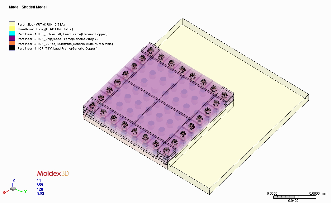
Case study of Capillary Underfill (CUF)
Step 2 Launch the Process Wizard, select Capillary Underfill in the analysis types, switch to the Underfill Setting tab, and then click Advanced to set contact angle parameters. In the Surface Tension tab, specify contact angle parameter at the interface of epoxy with each different component.
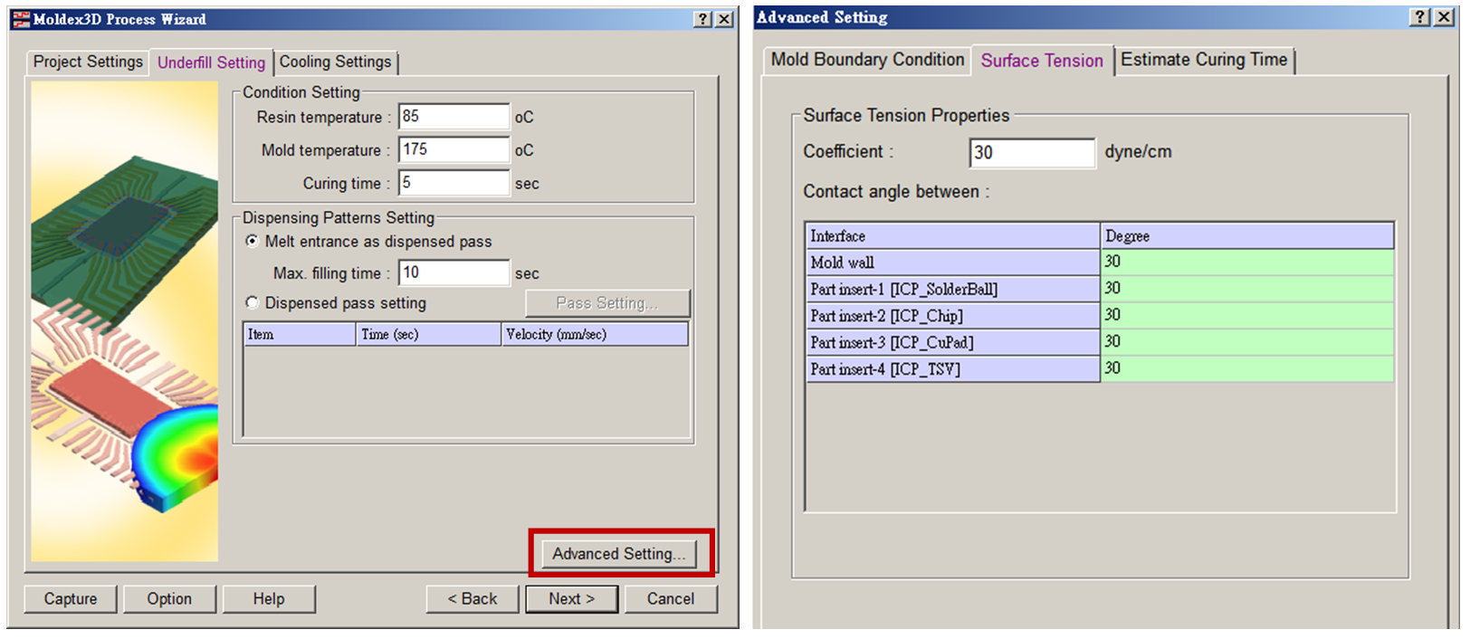
User interface of process wizard
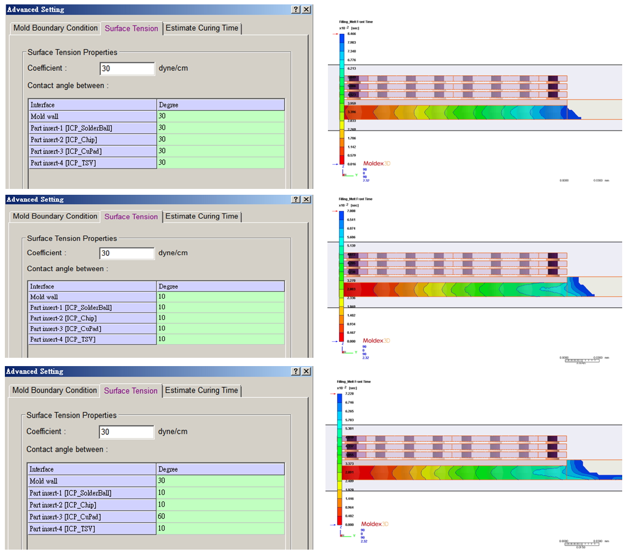
Step 3 After other project setting and filling analysis calculation are completed, the influences of different component contact angles in underfill flow front can be observed. There are three sets of contact angle settings in this case study: A. All of the contact angles are 30 degree; B. All of the contact angles are 10 degree; C. All of the contact angles are different values. According to the results, the flow front is significantly affected by different contact angle parameters, and show different filling trends.