Moldex3D 3D cooling system simulation supports the following analyses and the setting:
- The analysis of turbulence modeling
- The analysis of coolants surface roughness effect
- The selection of either pressure or flow rate inlet boundary condition
The following Tips and Tricks help Moldex3D users comprehend the application of 3D cooling analysis. Regarding the analysis of surface roughness effect and turbulence effect, proper parameters and selections are necessary to conduct simulation correctly. Please see the demonstration for the detail setting of 3D cooling analysis.
The Analysis of the Roughness Effect of the Turbulence Modeling
To launch the 3D cooling analysis, a solid coolant mesh is necessary. Also, the selection of “Run 3D solid cooling channel analysis” from the dropdown list under the Cool tab of Computation Parameter must be checked (see Fig. 1). In the default setting, the roughness value of the turbulence modeling is assigned as 0.02. Users can always change the surface roughness to suit their needs.
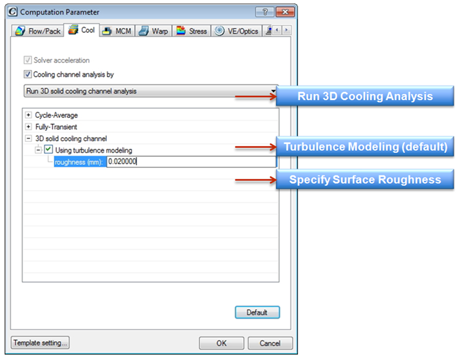 Fig. 1 Settings Under computation parameter/cool
3D cooling analysis output results include coolant velocity vector, streamline and coolant pressure which allows users to examine cooling flow behavior (see Fig. 2 & 3).
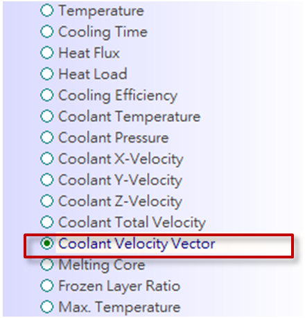 Fig. 2 3D cooling analysis output results
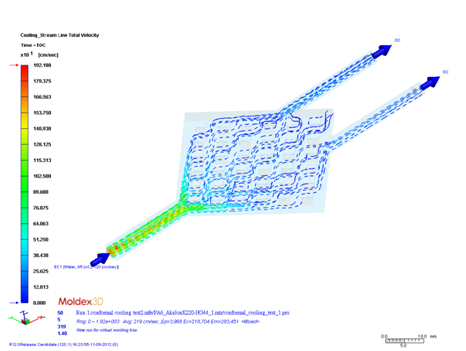
Fig. 3 Streamline result
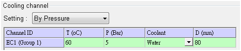
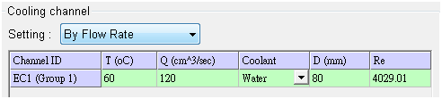
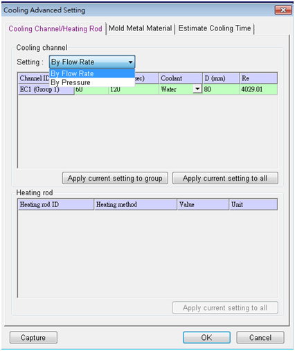
Select Inlet Boundary Condition
Within the tab of “Cooling Channel/ Heating Rod”, the inlet boundary condition of coolants can be specified as flow rate or pressure (see Fig. 6).